
Scanning Patient XRay beam XRay detector Intensity measurements Computer Memory Scanning Xray tube amp detectors rotate around patient All recent scanners Detectors measure radiation transmitted through patient for various pencil beam projections ID: 931309
Download Presentation The PPT/PDF document "Mathematics for Computed Tomography" is the property of its rightful owner. Permission is granted to download and print the materials on this web site for personal, non-commercial use only, and to display it on your personal computer provided you do not modify the materials and that you retain all copyright notices contained in the materials. By downloading content from our website, you accept the terms of this agreement.


Slide1
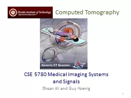
Mathematics for Computed Tomography
Slide2Scanning
Patient
X-Ray beam
X-Ray detector
Intensity
measurements
Computer
Memory
Slide3ScanningX-ray tube & detectors rotate around patient
(All recent scanners)
Detectors measure radiation transmitted through patient for various pencil beam projections
Relative transmission calculatedFraction of beam exiting patient
Patient
X-Ray beams
Slide4CT Detectorselectronic / quantitative
extremely sensitive
small radiation input differences measureable
output digitized & sent to computer
Slide5Photon PhateWhat can happen to an x-ray photon passing through a material (tissue)?
Material
Incoming X-ray
Photon
???
Slide6Photon Phate #1: Nothing
Photon exits unaffected
same energy
same directionGoodThese photons form the CT image
Material
Incoming X-ray
Photon
Outgoing X-ray
Photon
Slide7Photon Phate #2: Absorption
Photon disappears
Its energy is absorbed by material
GoodCreates differential absorption which forms CT imageBadSource of patient dose
Material
Incoming X-ray
Photon
Slide8Photon Phate #3: Scatter
Lower energy photon emerges
energy difference deposited in material
Photon usually emerges in different directionBadDegrades image
Material
Incoming X-ray
Photon
Outgoing X-ray
Photon
Slide9Photon Beam AttenuationAnything which removes original photon from beam
absorption
scatter
Material
Incoming X-ray
Photon
Absorption
Material
Incoming X-ray
Photon
Outgoing X-ray
Photon
Scatter
Slide10Example Beam Attenuation(Mono-energy source)
Each cm of material reduces beam intensity 20%
exiting beam intensity 80% of incident for 1 cm absorber
1cm
1cm
1cm
1cm
100
100 * .8 =
80
80 * .8 =
64
64 * .8 =
51
51 * .8 =
41
Slide11Attenuation Equation forMono-energetic Photon Beams
I = I
o
e
-mx
I = Exiting beam intensity
Io = Incident beam intensitye = constant (2.718…)m = linear attenuation coefficientproperty ofabsorber materialbeam energyx = absorber thickness
Material
I
o
I
x
For photons which are neither absorbed nor scattered
Slide12More Realistic CT Example Beam Attenuation for non-uniform Material
4 different materials
4 different attenuation coefficients
#
1?
#
2?
#
3?
#
4
?
m
1
m
2
m
3
m
4
I
o
I
x
I = I
o
e
-(
m
1
+
m
2
+
m
3
+
m
4
)x
Slide13Effect of Beam Energy on Mono-energetic Beam Attenuation
Low energy photons more easily absorbed
High energy photons more penetrating
All materials attenuate a larger fraction of low than high energy photons
Material
100
80
Higher
-energy
mono-energetic
beam
<80
Material
Lower
-energy
mono-energetic
beam
100
Slide14Attenuation Coefficient & Beam Energy
m
depends on beam
energy as well as material
#1?
#
2?
#
3
?
#
4
?
m
1
m
2
m
3
m
4
I
o
I
x
I = I
o
e
-(
m
1
+
m
2
+
m
3
+
m
4
)x
I = I
o
e
-
m
x
Slide15Mono-energetic X-ray Beams
Available from radionuclide sources
Not used in CT
Radionuclide intensity much lower than that of x-ray tube
Slide16X-ray Tube Beam
High intensity
Produces
poly-energetic beamCharacteristic radiationBremsstrahlung
#1
#2
#3
#4
m
1
m
2
m
3
m
4
I
o
I
I = I
o
e
-(
m
1
+
m
2
+
m
3
+
m
4
)x
Mono-energetic beam equation!
x
Slide17Beam Hardening Complication
Beam quality changes as it travels through absorber
greater fraction of low-energy photons removed from beam
Average beam energy increases
1cm
1cm
1cm
1cm
Fewer
Photons but
kV
avg
(B)
>
kV
avg
(A)
A
B
C
D
E
Fewer
Photons but
kV
avg
(C)
>
kV
avg
(B)
Fewer
Photons but
kV
avg
(D)
>
kV
avg
(C)
Fewer
Photons but
kV
avg
(E)
>
kV
avg
(D)
Slide18Beam Hardening Complication
Attenuation coefficients
m
n depend on beam energy!!!Beam spectrum incident on each block unknownFour m’s, each for a different & unknown energy
m
1
m2
m
3
m
4
1cm
1cm
1cm
1cm
I = I
o
e
-(
m
1
+
m
2
+
m
3
+
m
4
)x
Slide19Reconstruction
Scanner measures “I” for thousands of pencil beam projections
Computer calculates tens of thousands of attenuation coefficients
one for each pixelComputer must correct for beam hardeningeffect of increase in average beam energy from one side of projection to other
I = I
oe-(m1+m2+m3+m
4 +...)x
Slide20Why is CT done with High kV’s?Less dependence of attenuation coefficient on photon energy
Attenuation coefficient changes less at higher
kV’s
High kV provides high radiation flux at detector
Slide21Image Reconstruction
One of these equations for every projection line
I
A
= I
o
e
-(
m
A1
+
m
A2
+
m
A3
+
m
A4
+
...
)x
Projection
#A
I
C
= I
o
e
-(
m
C
1
+
m
C
2
+
m
C
3
+
m
C
4
+
...
)x
Projection
#C
Projection
#B
I
B
= I
o
e
-(
m
B1
+
m
B2
+
m
B3
+
m
B4
+
...
)x
Slide22Image Reconstruction
I
A
= I
oe-(mA1+mA2
+mA3+mA4 +...)x
IB = Ioe
-(
mB1+m
B2+mB3+
mB4 +...
)x
I
C
= I
oe
-(mC1
+mC2
+mC3+
mC4 +
...)x
Projection #A
Projection #BProjection #C
IA, I
B
, I
C
, ...
What We Measure:
m
A1
,
m
A2
,
m
A3
, ...
Reconstruction Calculates:
m
B1
,
m
B2
,
m
B3
, ...
m
C1
,
m
C2
,
m
C3
, ...
Etc.
*
The equations
Slide23CT (Hounsfield) Number
Calculated from reconstructed pixel attenuation coefficient
(m
t
- mW)CT # = 1000 X ------------ m
W
Where:ut = linear attenuation coefficient for tissue in pixeluW = linear attenuation coefficient for water
Slide24CT Numbers for Special Stuff
Bone: +1000
Water: 0
Air: -1000
(mt - mW
)CT # = 1000 X ------------ mW