
I mpact on OpenLoop SUMIMO Date 20161104 Slide 1 Authors Introduction In 1 11ay has agreed to have multiple options of GI In 4 simulation results suggested GI32 symbols was sufficient for up to MCS 12 in a NLOS cubicle scenario During the September meeting there were sug ID: 933600
Download Presentation The PPT/PDF document "GI and P hase I mpairments" is the property of its rightful owner. Permission is granted to download and print the materials on this web site for personal, non-commercial use only, and to display it on your personal computer provided you do not modify the materials and that you retain all copyright notices contained in the materials. By downloading content from our website, you accept the terms of this agreement.


Slide1
GI and Phase Impairments Impact on Open-Loop SU-MIMO
Date: 2016-11-04
Slide 1
Authors:
Slide2Introduction
In [1], 11ay has agreed to have multiple options of GI
In [4], simulation results suggested GI=32 symbols was sufficient for up to MCS 12 in a NLOS cubicle scenario. During the September meeting, there were suggestions to further investigate the impacts of phase noise impairments with a shorter GI.
This contribution investigates the use of shorter GI in specific scenarios.
CFO and/or phase noise with realistic channel estimationPerformance results show that in certain scenarios the use of a shorter GI is justified.
Slide
2
Slide3PPDU Format in 802.11ayCurrent EDMG PPDU format for SC PHY[1]:EDMG preamble part introduces extra overhead
Even though multi data stream transmissions can be applied to data part, EDMG transmission may not be always be as efficient as legacy DMG transmission. Overhead reduction is desirable for EDMG PPDU
Slide
3
Slide4Guard IntervalIn 802.11ad, SC data blocks (448 symbols ) are separated by guard intervals (64 symbols).
The 64 GI symbols are modulated symbols from a Golay sequence. The usage of GI:GI is a time period to mitigate inter-block interference GI functions
as a cyclic prefix which allows the use of frequency domain equalizer (FDE) at
the receiverGI is a periodic known sequence to assist with AGC and phase trackingHowever, GI is extra overhead for data transmission. Is 64 GI always necessary?In this contribution,
a different GI size is evaluated using link level simulation.We focus on the impact from the phase-related impairments and how GI length impacts the effectiveness of mitigation mechanisms.
Slide
4
64
448 symbols
64
448 symbols
64
448 symbols
64
Slide5Simulation AssumptionsBased on 11ad SC PHY Spatial stream parser:
MCS index is the same for all streams per PPDU, and a single CRC is used per PPDU2 spatial streams, configuration 4 in [2]MMSE receiver with FDE
realistic channel estimation at
receiver based on the agreed EDMG CEF [1]Enterprise cubicle scenario in 11ay/ad channel model [2]STAs are randomly placed
in the cubicle 1 in the center of the CR, 0.9m above the floorAP is positioned at x=2.8, y=6, z=2.9m on the ceiling
Detailed assumptions can be found in the appendix
PSDU size is 8192 bytes
b1
b2
b3
b4
b5
b6
b1
b3
b5
b2
b4
b6
Encoder Output Bits
Stream 1
Stream 2
Slide 6
Slide6Phase Noise Model & CFOPhase noise modelAs in [5]
All rx antennas share the same noise with
PSD(0) =
-
90
dBc
/Hz
Pole frequency
f
p
= 1 MHz
I
ndependent
white noise with
PSD
=
-
130
dBc
/Hz for each
rx
antenna
CFO is assumed to be
13.675 ppm at the receiver, shared by all antennas
Slide
6
Source: [5]
Slide7Phase correction
Equalized GI from previous block k-1 and current block k are compared to GI to acquire
and
Equalized data symbol j at block
k
is
corrected
by
,
N
= 512 –
Same phase correction method is used for both residual CFO and phase noise mitigation
Slide
7
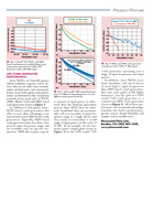
Slide8PER performance (MCS12) Slide 8
CFO error-onlyPHN error-only
Slide9PER performance (MCS12)-cont’dSlide 9Phase noise has
large impactsTracking mechanism improves performance to some degree, but not sufficient in NLOS channel with a small GIShorter GI length has almost no impact on CFO correction
CFO+PHN
errors
Slide10PER performance (MCS9) Slide 10
CFO error-onlyPHN error-only
Slide11PER performance (MCS9)-cont’dSlide 11
Phase noise has small impact regardless of GI length, or tracking Shorter GI length has almost no impact on CFO correction
CFO+PHN
errors
Slide12PER performance (MCS5) Slide 12
CFO error-onlyPHN error-only
Slide13PER performance (MCS5)-cont’dSlide 13
Phase noise has almost no impact regardless of GI length, or tracking Shorter GI length has almost no impact on CFO correction
CFO+PHN
errors
Slide14Slide 14Conclusions
In [4], GI overhead analysis shows ~7% of gains of GI=32 over GI=64
Phase noise has small impact on BPSK/QPSK MCSs regardless of GI length and with or without correction
Phase noise has impact on MCS12 or higher order modulations at least in a NLOS channel with a small GI
GI=32 has similar performance as GI=64 up to MCS9(QPSK)
Slide15Straw PollDo you agree to add the following block format in 11ay SFD:(32 GI,480 data) symbols per SC block for a 2.16GHz channel is an option for SC PHY in QPSK/BPSK MCSSlide
15
Slide16Slide 16References
Carlos Cordeiro, “Specification Framework for TGay”, IEEE 802.11-15/01358r6
A.
Maltsev, et al, “Channel models for
ieee 802 11ay”, IEEE doc. 11-15/1150r7 R.
Maslennikov
,
et al
,
“
Implementation of 60 GHz WLAN Channel Model
,
”
IEEE doc.
11-10/0854r3.
L. Sun
et al
, “
GI Overhead/Performance Impact on Open-Loop SU-MIMO
”
IEEE doc. 11-16/1172r1.
K. Zeng et al, “Considerations on Phase Noise Model for 802.11ay ”
IEEE doc. 11-16/0390r1
Slide17AppendixSlide 17
Slide18Channel parametersFor channel with LOS components [3], TX/RX analog beamforming
for both polarizations of PAA#i are based on the LOS direction between TX PAA#i ↔ RX PAA#i
For channel without LOS componentsBeam forming based on the
AoD/AoA of strongest signal path between TX PAA#i ↔ RX PAA#i
Channel bandwidth 2.64 GHz, center frequency 60.48 GHzEach PAA has 2 elementsDistance between antenna elements 0.0025mDistance between center of PAAs 10cm
For AP-STA scenario, STA is placed at a plane 2m below AP in the cubicle 1. Random rotation around z-axis between STA/AP
.
Slide
18