
POC PawelChwalowskinasagov Objectives Use current state of the art coupled CFD tools in a predictive manner coupled structural dynamics unsteady aerodynamics Apply to configuration and test conditions that challenge the range of application of the modeling ie physics are challengin ID: 933206
Download Presentation The PPT/PDF document "AePW-3: High Angle of Attack Working Gr..." is the property of its rightful owner. Permission is granted to download and print the materials on this web site for personal, non-commercial use only, and to display it on your personal computer provided you do not modify the materials and that you retain all copyright notices contained in the materials. By downloading content from our website, you accept the terms of this agreement.


Slide1
AePW-3: High Angle of Attack Working GroupPOC: Pawel.Chwalowski@nasa.gov
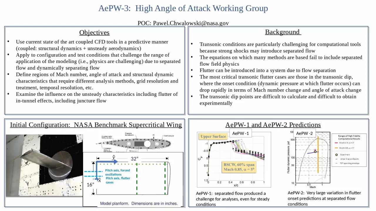
Objectives
Use current state of the art coupled CFD tools in a predictive manner (coupled: structural dynamics + unsteady aerodynamics)
Apply to configuration and test conditions that challenge the range of application of the modeling (i.e., physics are challenging) due to separated flow and dynamically separating flowDefine regions of Mach number, angle of attack and structural dynamic characteristics that require different analysis methods, grid resolution and treatment, temporal resolution, etc.Examine the influence on the unsteady characteristics including flutter of in-tunnel effects, including juncture flow
Background
Transonic conditions are particularly challenging for computational tools because strong shocks may introduce separated flow
The equations on which many methods are based fail to include separated flow field physicsFlutter can be introduced into a system due to flow separationThe most critical transonic flutter cases are those in the transonic dip, where the onset condition (dynamic pressure at which flutter occurs) can drop rapidly in terms of Mach number change and angle of attack changeThe transonic dip points are difficult to calculate and difficult to obtain experimentally
Initial Configuration: NASA Benchmark Supercritical Wing
Model planform. Dimensions are in inches.
32
”
16
”
Pitch axis, forced oscillations
Pitch axis, flutter cases
AePW-1 and AePW-2 Predictions
AePW-1: separated flow produced a challenge for analyses, even for steady conditions
AePW-2: Very large variation in flutter onset predictions at separated flow conditions
AePW
-1
AePW
-2
Slide2AePW-3: High Angle of Attack Working GroupPOC: Pawel.Chwalowski@nasa.gov
Mach 0.8,
AoA
= 5° condition
in R-134a has been chosen
for initial analyses challenge
Existing Data
Separated flow assessment, using data from 1992 testing
R-12, Mach 0.8 Flutter Points, 1992
R-12, Flutter Points,
a
=0°, 1992
AePW-3
Predictions to date at Mach 0.8,
AoA
= 5
°
2
Experimental data,
Mach 0.8,
AoA
~ 5◦Current Time-DomainCalculationsCurrent Frequency –Domain Calculations
Computational
and Experimental Plans
Perform input uncertainty analyses (geometry, angle of attack, elastic axis location, analysis method parameters)
Conduct additional wind tunnel testing:
Measure the flutter boundaries including the front, bottom, and backsides of the flutter buckets
Acquire global detailed subcritical data sets:
Digital image correlation measurements for static and time-accurate model motion and deformation
Unsteady pressure sensitive paint for on-surface quantitiesUnsteady particle image velocimetry for off-body velocitiesAcquire repeat data pointsQuantify (measure) the flow environment