
Greg Spaeth Project Engineer Materials Engineering Laboratory Plastics Engineering Company Presented at 2013 SPE Thermoset Division TOPCON Phenolic Resins Phenolic resins are synthesized in a pressure vessel by repeatedly linking phenolic monomers with aldehyde chemicals ID: 933293
Download Presentation The PPT/PDF document "Phenolic Resins and Phenolic Molding C..." is the property of its rightful owner. Permission is granted to download and print the materials on this web site for personal, non-commercial use only, and to display it on your personal computer provided you do not modify the materials and that you retain all copyright notices contained in the materials. By downloading content from our website, you accept the terms of this agreement.


Slide1
Phenolic Resins
and Phenolic Molding Compounds
Greg SpaethProject Engineer,Materials Engineering LaboratoryPlastics Engineering Company
Presented at 2013 SPE Thermoset Division TOPCON
Slide2Phenolic Resins
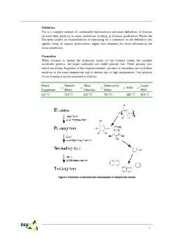
Slide3Phenolic resins are synthesized in a pressure vessel by repeatedly linking phenolic monomers with aldehyde chemicalsTypically
phenol and formaldehydeCresol Cashew nutshell oil
FurfuralProcess variations can result in a assortment of resin structures each demonstrating a wide range of properties
Other phenols include
Another aldehyde used
Slide4There are Two Types of Phenolic Resins Novolac
Molar excess of phenolRequire an external curing agent
Usually hexamethylenetetramine or “Hexa”
Two Stage
Two year shelf life
Resol
Typically there is a molar excess of formaldehyde
Do not require an external curing agent
Single Stage
Six month shelf life
Slide5Phenolic Molding Compounds
Slide6Phenolic Molding Compounds
Phenolic Molding Compounds are produced by compounding various fillers with Phenolic Resin
Typical Formula50 % Phenolic Resin, resol or novolac
45 % filler5 % colorants and lubricants
Woodflour
Glass Fibers
Cotton
Carbon Fibers or graphite powder
Minerals, talc, clay, ATH, etc.
Carbon Black
Zinc Stearate
Slide7The Oil and Natural Gas
Mining Process
as a Case Study for
Phenolic Materials
Slide8A well begins by drilling a large diameter hole extending below the fresh water
Slide9A surface casing is inserted to isolate fresh water and support the blow out preventer
Slide10Cement is pumped into the casing
Slide11The cement is forced out of the casing and up the well hole sealing of the aquifer
Slide12Wiper Plugs and Darts
Phenolic Core
Over molded rubber shell
Slide13Easy drill out with small debrisThe molded phenolic core provides superior strength and rigidity to enable the wiper plug to withstand the high pressures involved in forcing hundreds of cubic feet of concrete through the well casing
Why Phenolic Molding Compounds?High Modulus provides stiffness and stability for the
darts mandrel core and tighter griping for the elastomer wiper segmentsHeat resistance allowing plugs rated for use at 400ºF
Slide14The wiper plug is then drill out and the production well is drilled.
Slide15Production casing is lowered
It
takes
more than 350 casings weighing more then 85 tons to case a 10,500 foot well
Slide16Cement is once again pumped into the well
Slide17Again using a wiper plug the cement is force back up the well securing the casing
Slide18Fracturing the well then begins by lowering a perforation gun down the well casing
Slide19Small shaped explosives blast holes through the
casing, cement, and
into the formation
Slide20Fracturing
fluid is pumped into the well
Slide21The fluid under extreme pressure causes the formation to fracture
Slide22F
racturing fluids varies among regions and well types, but typically consists of
water (90+%) proppant (9%) and chemicals (<2%)
Resin Coated Proppant Sand
Slide23Resin Coated Proppant Sand
Once the fracturing fluid is removed, the phenolic resin coated sand remains
behind
and works as
a prop to keep the
fissures
from sealing on release of
pressure
Slide24Phenolic’s high modulus and excellent heat and creep resistance resists fracture under pressure as proven in industry “Conductivity test”
Why Phenolic Resin?
Slide25Chemical Resistance harsh chemicals found down hole can attack various proppant including ceramic proppant
Why Phenolic Resin?Curable Proppant Enables the proppant to remain in place in wells with high pressure flow
Slide26The now fractured portion of the well is sealed off using fracturing ball
Slide27Fracturing Balls
Slide28Fracturing Balls
Slide29Customizable formulations allowing a specific gravity range of 0.8 to 3.5+Phenolic Balls offer an excellent combination of chemical and heat resistance with superior tensile and compressive strength compared with other plastic balls.
Why Phenolic Molding Compound?
Slide30The
perf
gun is again lowered and detonated
Slide31Again fracturing fluid is pumped into the well to fracture the new section of the well while the already fractured section is isolated by the frac ball
The
perf
gun is again lowered and detonated
Slide32Fracturing Balls
Slide33Perforation and well fracturing is repeated as often as needed
Slide34Once fracturing is complete the balls are usually drilled or floated out
Slide35Surface equipment is put in place
Slide36Well begins production
Slide37Valve Components
Slide38Valve Components
Slide39A phenolic back-up ring allows internal pressure to anchor the seat within the valve body and prevents seat walking
Non-collapsible, stretch resistant, blow out proof, field replaceableNon-collapsible, stretch resistant, blow out proof, field replaceable
Why Phenolic Molding Compounds?Strength, rigidity, dimensional stability, creep resistance
Chemical resistance and high hardnessProvide valve components that resists corrosive environments and do not deform under pressure allowing for repeated ball sealing
Slide40Corrosive coatings for Storage tanks, semi tank trailers, railroad
tank cars, fans blowers, and fin tube coilsOther Applications
Binder for Friction pads, brake pads, grinding wheels, plywood and particle board
Wear Resistance Gas meter valves, pump seals, caster wheels
Dimensional Stability &Thermal Performance
Brake pistons, transmission parts, electrical motor brush cards
Electrical insulation
terminal strips,
commutators
, capacitor cans and caps
Slide41Offshore Applications
Slide42Why Phenolic Resin?
Superior Creep Resistance Strength and stability under loadLow weight high strength and modulus Strength and rigidityChemically Resistant
Harsh marine environmentExcellent flammability resistance and low smoke and toxicity
Increased level of safetyHigh carbon and char yield
Retains level of strength and integrity should fire break out
Slide43Chemical Resistance
Phenolic PropertiesTransmission oil,150ºC (302ºF)Salt water, 65ºC (150ºF)
Beach, 65ºC (150ºF)Unleaded gasoline, 22ºC (72ºF)E85 Unleaded gasoline, 22ºC (72ºF)
SAE 30 Motor oil, 150ºC (302ºF)Propylene glycol, 100ºC (212ºF)
Crude oil
, 22ºC (72ºF
)
Slide44Chemical Resistance
Phenolic Properties
Slide45Chemical Resistance
Phenolic Properties
Slide46Chemical Resistance
Phenolic Properties
Slide47Chemical Resistance
Phenolic Properties
Slide48Chemical Resistance
Phenolic Properties
Slide49Comparison of Phenolic molding compound to engineering grade thermoplasticsPhenolic Properties
Data for PLENCO materials available from PLENCO.com, all thermoplastic data from matweb.com overview average valuesThermoplastics
20% fiber glass filled ABS 20% fiber glass filled Acetal 20% fiber glass filled PPA 20% fiber glass filled PPS 20% fiber glass filled Nylon66Phenolic Molding Compound
Glass and mineral filled PLENCO 06404 glass and mineral filled PLENCO 02311 general purpose woodflour filled
Slide50HardnessPhenolic Properties
Data for phenolic and
PLENCO materials are approximated from E scaleData for
PLENCO materials available from PLENCO.com, all thermoplastic data from matweb.com overview average values
Slide51Strength and modulusPhenolic Properties
Data for
PLENCO materials available from PLENCO.com, all thermoplastic data from matweb.com overview average values
Slide52Strength and modulusPhenolic Properties
Data for
PLENCO materials available from PLENCO.com, all thermoplastic data from matweb.com overview average values
Slide53Compressive StrengthPhenolic Properties
Data for
PLENCO materials available from PLENCO.com, all thermoplastic data from matweb.com overview average values
Slide54Heat ResistancePhenolic Properties
Slide55Flammability resistancePhenolic Properties
UL V-0 at 0.5mmIEC 60695 Glow Wire GWFI and GWFI Rating 960ºC+ at 0.75mm
ASTM E162 Flame Spread 0.85**Source: Composites WorldAuthor: Michael LeGault Posted on: 2/14/2013
Slide56Post bake
Phenolic PropertiesWhat is it?
Postbaking is a manufacturing step where molded parts are heated in an oven after being removed from the die.
Why do it?
Dimensional stabilize a part, especially for high temperature applications
Out-gas residual ammonia which is a by product of two stage cure
Improve strength
Sometimes only because the print tells you to
How is it done?
Ramp oven from room temperature to 15ºC below parts initial
t
g
at 5º/min
Ramp
oven to desired temperature at 0.5-0.25ºC/min to keep the oven temperature under the parts instantaneous
t
g
Do I need to do it?Many Applications do not require a postbake, only a thorough understanding of the reasons to postbake will help you answer this question
Slide57Thank You
Questions?
Greg SpaethProject Engineer,Materials Engineering LaboratoryPlastics Engineering Company
Presented at 2013 SPE Thermoset Division TOPCON