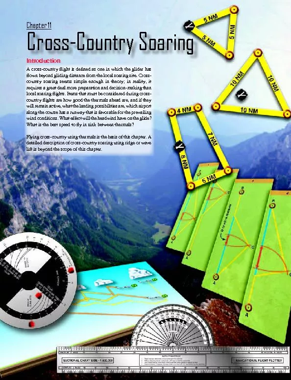
/
A cross-country �ight is de�ned as one in which A cross-country �ight is de�ned as one in which

A cross-country �ight is de�ned as one in which - PDF document

alexa-scheidler
alexa-scheidler . @alexa-scheidler
Follow
403 views
Uploaded On 2016-06-09

A cross-country �ight is de�ned as one in which - PPT Presentation

111 CrossCountry Soaring Chapter 11 112Figure 111 Excerpt from a Sectional Aeronautical Chart Adequate soaring skills form the basis of the pilotx2019s preparation for crosscountry soaring ID: 354306

11-1 Cross-Country Soaring Chapter 11 11-2Figure 11-1. Excerpt

Share:

Link:

Embed:

Download Presentation from below link

Download Pdf The PPT/PDF document "A cross-country �ight is de&#..." is the property of its rightful owner. Permission is granted to download and print the materials on this web site for personal, non-commercial use only, and to display it on your personal computer provided you do not modify the materials and that you retain all copyright notices contained in the materials. By downloading content from our website, you accept the terms of this agreement.


Presentation Transcript

11-1 A cross-country �ight is de�ned as one in which the glider has �own beyond gliding distance from the local soaring site. Cross-country soaring seems simple enough in theory; in reality, it requires a great deal more preparation and decision-making than local soaring �ights. Items that must be considered during cross-country �ights are how good the thermals ahead are, and if they will remain active, what the landing possibilities are, which airport along the course has a runway that is favorable for the prevailing wind conditions. What effect will the headwind have on the glide? Flying cross-country using thermals is the basis of this chapter. A detailed description of cross-country soaring using ridge or wave Cross-Country Soaring Chapter 11 11-2Figure 11-1. Excerpt from a Sectional Aeronautical Chart. Adequate soaring skills form the basis of the pilot’s preparation for cross-country soaring. Until the pilot has �own several �ights in excess of 2 hours and can locate and utilize thermals consistently, the pilot should focus on improving those skills before attempting cross-country �ights.Any cross-country �ight may end in an off-�eld landing, so short-�eld landing skills are essential. These landings should be practiced on local �ights by setting up a simulated off-�eld landing area. Care is needed to avoid interfering with the normal �ow of traf�c during simulated off-�eld landings. The �rst few simulated landings should be done with an instructor, and several should be done without the use of the altimeter.The landing area can be selected from the ground, but the best training is selecting one from the air. A self-launching glider or other powered aircraft for landing area selection training and simulated approaches to these areas is a good Once soaring skills have been honed, the pilot needs to be able to determine position along a route of �ight. A Sectional Aeronautical Chart, or sectional, is a map soaring pilots use during cross-country �ights. They are updated every 6 months and contain general information, such as topography, cities, major and minor roads and highways, lakes, and other features that may stand out from the air, such as a ranch in an otherwise featureless prairie. In addition, sectionals show the location of private and public airports, airways, restricted and warning areas, and boundaries and vertical limits of different classes of airspace. Information on airports includes �eld elevation, orientation and length of all paved runways, runway lighting, and radio frequencies in use. Each sectional features a comprehensive legend. A detailed description of the sectional chart is found in FAA-H-8083- 25, the Pilot’s Handbook of Aeronautical Knowledge. shows The best place to become familiar with sectional charts is on the ground. It is instructive to �y some “virtual” cross-country �ights in various directions from the local soaring site. In addition to studying the terrain (hills, mountains, large lakes) that may affect the soaring along the route, study the various lines and symbols. What airports are available on course? Do any have a control tower? Can all the numbers and symbols for each airport be identi�ed? If not, �nd them on the legend. Is there Class B, C, or D airspace en route? Are there any restricted areas? Are there airways along the �ightpath? Once comfortable with the sectional from ground study, it can be used on some local �ights to practice locating Any cross-country �ight may end with a landing away from the home soaring site, so pilots and crews should be prepared for the occurrence prior to �ight. Sometimes an aerotow retrieve can be made if the �ight terminates at an airport; however, trailer retrieval is more typical. Both the trailer and tow vehicle need a pre�ight before departing on the �ight. The trailer should be roadworthy and set up for the speci�c glider. Stowing and towing a glider in an inappropriate trailer can lead to damage. The driver should be familiar with procedures for towing and backing a long trailer. The tow vehicle should be strong and stable enough for towing. Both radio and telephone communication options should be Before any �ight, obtain a standard brie�ng and a soaring forecast from the Automated Flight Service Station (AFSS). As discussed in Chapter 9, Soaring Weather, the briefer supplies general weather information for the planned route, as well as any NOTAMs, AIRMETs, or SIGMETs, winds aloft, an approaching front, or areas of likely thunderstorm activity. Depending on the weather outlook, beginners may �nd it useful to discuss options with more experienced cross-Many pilots have speci�c goals in mind for their next cross-country �ight. Several options should be planned ahead based on the area and different weather scenarios. For instance, if the goal is a closed-course 300 nautical mile (NM) �ight, several likely out-and-return or triangle courses should be laid out ahead of time, so that on the speci�c day, the best task can be selected based on the weather outlook. There are numerous �nal details that need attention on the morning of the �ight, so special items should be organized and readied Lack of preparation can lead to delays, which may mean not enough of the soaring day is left to accomplish the planned �ight. Even worse, poor planning leads to hasty last-minute preparation and a rush to launch, making it easy to miss Inexperienced and experienced pilots alike should use checklists for various phases of the cross-country preparation in order to organize details. When properly used, checklists can help avoid oversights, such as sectionals left at home, barograph not turned on before takeoff, etc. Checklists also aid in making certain that safety of �ight items, such as all assembly items, are checked or accomplished, oxygen turned on, drinking water is in the glider, etc. Examples of checklists Items to take to the gliderport (food, water, battery, Assembly must follow the Glider Flight Manual/Pilot’s Operating Handbook (GFM/POH) and add Prelaunch (water, food, charts, glide calculator, Brie�ng checklist for tow pilot, ground crew, and Being better organized before the �ight leads to less stress Many items not required for local soaring are needed for cross-country �ights. Pilot comfort and physiology is even more important on cross-country �ights since these �ights often last longer than local �ights. An adequate supply of drinking water is essential to avoid dehydration. Many pilots use the backpack drinking system with readily accessible hose and bite valve that is often used by bicyclists. This system is easily stowed beside the pilot, allowing frequent sips of water. A relief system also may be needed on longer �ights. Cross-country �ights can last up to 8 hours or more, Several items should be carried in case there is an off-�eld landing. (For more details, see Chapter 8, Abnormal and Emergency Procedures.) First, a system for securing the glider is necessary, as is a land-out kit for the pilot. The kit varies depending on the population density and climate of the soaring area. For instance, in the Great Basin in the United States, a safe landing site may be many miles from the nearest road or ranch house. Since weather is often hot and dry during the soaring season, extra water and food should be added items. Taking good walking shoes is a good idea as well. A cell phone may prove useful for landouts in areas with some telephone coverage. Some pilots elect to carry an Emergency Position Indicating Radio Beacon (EPIRB) in Cross-country soaring requires some means of measuring distances to calculate glides to the next source of lift or the next suitable landing area. Distances can be measured using a sectional chart and navigational plotter with the appropriate scale, or by use of Global Positioning System (GPS). If GPS is used, a sectional and plotter should be carried as a backup. A plotter may be made of clear plastic with a straight edge on the bottom marked with nautical or statute miles for a sectional scale on one side and World Aeronautical Chart (WAC) scale on the other. On the top of the plotter is a protractor or semicircle with degrees marked for measuring course angles. A small reference index hole is located in the center of the semicircle. Prior to taking off, it may be handy to prepare a plotter for the speci�c glider’s performance by applying some transparent tape over the plotter marked with altitudes versus range rings in still air. After a little use, the glider pilot should gain a perception of the glide angle most often evident in the conditions of the day.Glide calculations must take into account any headwind or tailwind, as well as speeds to �y through varying sink rates as discussed in chapter 5. Tools range widely in their level 11-4Figure 11-2. Navigational plotter. 1. Place hole over intersection of true course and true north line.2. Without changing position rotate plotter until edge is over true course line.3. From hole follow true north line to curved scale with arrow pointing in direction of flight.4. Read true course in degrees, on proper scale, over true north line. read scales counter-clockwise. Figure 11-3. Circular glider calculator. RATE OFSPEED TO FLY (KTS) HEAD WING TAIL WINDTAIL WING HEAD WIND of sophistication, but all are based on the performance polar for the particular glider. Most high-performance gliders usually have glide/navigation computers that automatically computer the glide ratio (L/D). The simplest glide aid is a table showing altitudes required for distance versus wind, which can be derived from the polar. To avoid a table with too many numbers, which could be confusing, some interpolation is often needed. Another option is a circular glide calculator as shown in . This tool allows the pilot to read the altitude needed for any distance and can be set for various estimated headwinds and tailwinds. Circular glide calculators also make it easy to determine whether a pilot is actually achieving the desired glide, since heavy sink or a stronger-than-estimated headwind can cause a loss of more height with distance than was indicated by the calculator. For instance, the settings in Figure 11-3 indicate that for the estimated 10 knot headwind, 3,600 feet is required to glide 18 miles. After gliding 5 miles, there is still 2,600 feet. Note that this only The pilot can also use simple formulas to mentally compute an estimated L/D.One hundred feet per minute (fpm) is approximately 1 knot. To compute your glide ratio, take groundspeed divided by vertical speed as indicated on a vertical speed indicator (VSI) or variometer, then divide by 100 (just drop the zeros). If groundspeed is not available, use indicated airspeed, which will not yield as accurate a result as groundspeed. In this case, groundspeed or indicated airspeed is 60 knots. VSI shows 300 fpm down. Calculate the glide ratio.Another method is to basically recompute a new L/D by utilizing this standard formula. Glide ratio, with respect to the air (GRA) or L/D, remains constant at a given airspeed. For example, your glider’s glide ratio, lift over drag (L/D) is 30 to 1 expressed as 30:1 at a speed of 50 knots. At 50 knots with an L/D of 30:1, a 10-knot tailwind results in an 11-3 In addition to a glide calculator, a MacCready ring on the variometer allows the pilot to easily read the speed to �y for different sink rates. MacCready rings are speci�c to the type of glider and are based on the glider performance polar. (See Chapter 4, Flight Instruments, for a description of the MacCready ring.) Accurately �ying the correct speed 11-5Figure 11-4. Glide calculation example. Glider specificationsGlide ratio (L/D) = 30:1Speed (GRA) = 50 knots 50 + 10 = 60 60/50 = 1.2 1.2 x 30 = 36 50 − 10 = 40 40/50 = 0.8 0.8 x 30 = 24 x L/D = Effective L/D( ) Many models of electronic glide calculators now exist. Often coupled with an electronic variometer, they display the altitude necessary for distance and wind as input by the pilot. In addition, many electronic glide calculators feature speed-to-�y functions that indicate whether the pilot should �y faster or slower. Most electronic speed-to-�y directors include audio indications, so the pilot can remain visually focused outside the cockpit. The pilot should have manual backups for electronic glide calculators and speed-to-�y directors in Other equipment may be needed to verify soaring performance to receive a Federation Aeronautique Internationale (FAI) badge or record �ights. These include turn-point cameras, barographs, and GPS �ight recorders. For complete descriptions of these items, as well as badge or record rules, check the Soaring Finally, a notepad or small leg-attached clipboard on which to make notes before and during the �ight is often handy. Notes prior to �ight could include weather information such as winds aloft forecasts or distance between turn points. In �ight, noting takeoff and start time, as well as time around any turn points, Airplane pilots navigate by pilotage (�ying by reference to ground landmarks) or dead reckoning (computing a heading from true airspeed and wind, and then estimating time needed to �y to a destination). Glider pilots use pilotage since they generally cannot remain on a course line over a long distance and do not �y one speed for any length of time. Nonetheless, it is important to be familiar with the concepts of dead reckoning since a combination of the two methods Measuring distance with the plotter is accomplished by using the straight edge. Use the Albuquerque sectional chart and measure the distance between Portales Airport (Q34) and Benger Airport (Q54), by setting the plotter with the zero mark on Portales. Read the distance of 47 nautical miles (NM) to Benger. Make sure to set the plotter with the sectional scale if using a sectional chart (as opposed to the WAC scale), otherwise the measurement will be off by a The true heading between Portales and Benger can be determined by setting the top of the straightedge along the course line, then slide it along until the index hole is on a line of longitude intersecting the course line. Read the true heading on the outer scale, in this case, 48°. The outer scale should be used for headings with an easterly component. If the course were reversed, �ying from Benger to Portales, use the inner scale, for a westerly component, to �nd 228°. A common error when �rst using the plotter is to read the course heading 180° in error. This error is easy to make by reading the scale marked W 270° instead of the scale marked E 09°. For example, the course from Portales to Benger is towards the northeast, so the heading should be somewhere between For training purposes, plan a triangle course starting at Portales Airport (PRZ), with turn points at Benger Airport (X54), and the town of Circle Back. As part of the pre�ight preparation, draw the course lines for the three legs. Using the plotter, determine the true heading for each leg, then correct for variation and make a written note of the magnetic heading on each leg. Use 9° east (E) variation as indicated on the sectional chart (subtract easterly variations, and add westerly variations). The �rst leg distance is 47 NM with a heading of 48° (48° – 9° E = 39° magnetic); the second leg is 38 NM at 178° true (178° – 9° E = 169° magnetic); the third leg is 38 NM at 282° true (282° – 9° E = 273° magnetic). Assume the base of the cumulus is forecast to be 11,000 MSL, and the winds aloft indicate 320° at 10 knots at 9,000 MSL and 330° at 20 knots at 12,000 MSL. Make a written note of the winds aloft for reference during the �ight. For instance, the �rst leg has almost a direct crosswind from the left; on the second leg, a weaker crosswind component from the right; while the �nal leg is almost directly into the wind. Knowing courses and approximate headings aids the navigation and helps avoid getting lost, even though deviations to stay with the best lift are needed. During the �ight, if the sky ahead 11-6Figure 11-6. Using the outer and inner scales of the navigation plotter. Portales Benger Airport Index hole True heading 48°or course reversal 228° Figure 11-5. Measuring distance using the navigation plotter. Portales Benger Airport 47 nautical miles 11-7Figure 11-7. Cross-country triangle. Portales Benger Airport Bovina Friona Clovis Clovis airport Salt Lake Needmore Arch Class D Airspace Muleshoe Muleshoe airport Circle Back shows several equally promising cumulus clouds, choosing During pre�ight preparation, study the course line along each leg for expected landmarks. For instance, the �rst leg follows highway and parallel railroad tracks for several miles before the highway turns north. The town of Clovis should become obvious on the left. Note the Class D airspace around Cannon Air Force Base (CVS) just west of Clovis—this could be an issue if there is better soaring north of course track because of military traf�c operating into Cannon. With the northwesterly wind, it is possible to be crossing the path of aircraft on a long �nal approach to the northwest-southeast Next is the Clovis airport (CVN) with traffic to check operating in and out of the airport. Following Clovis are Bovina and Friona; these towns can serve as landmarks for the �ight. The proximity of the Texico (TXO) VOR, a VHF Omnidirectional Range station near Bovina, indicates the need for alertness for power traf�c in the vicinity. The VOR The �rst turn point is easy to locate because of good landmarks, including Benger Airport (X54). [Figure 11-8] The second leg has fewer landmarks. After about 25 miles, the town of Muleshoe and the Muleshoe airport (2T1) should appear. The town should be on the right and the airport on the left of the intended course. Next, the course enters the Bronco 1 Military Operations Area (MOA). The dimensions of the 11-8Figure 11-8. Benger Airport (X54). Figure 11-9. Circle Back and Needmore. MOA can be found on the sectional chart, and the automated �ight service station (AFSS) should be consulted concerning the active times of this airspace. Approaching the second turn point, it is easy to confuse the towns of Circle Back and Needmore. The clues are the position of Circle Back relative to an obstruction 466 feet above ground level (AGL) and a road that heads north out of Needmore. Landmarks on the third leg include power transmission lines, Salt Lake (possibly dry), the small town of Arch, and a major road coming south out of Portales. About eight miles from After a thorough pre�ight of the glider and all the appropriate equipment is stowed or in position for use in �ight, it is time to go �y. Once in the air and on course, try to verify the winds aloft. Use pilotage to remain as close to the course line as soaring conditions permit. If course deviations become necessary, stay aware of the location of the course line to the next turn point. For instance, the Cu directly ahead indicates lift, but the one 30° off course indicates possibly even more lift, it may be better not to deviate. If the Cu left of course indicates a possible area of lift compared to the clouds ahead and only requires a 10° off course deviation, proceed towards the lift. Knowing the present location of the glider and where the course line is located is important for keeping situational awareness.Sometimes it is necessary to determine an approximate course once already in the air. Assume a few miles before reaching the town of Muleshoe, on the second leg, the weather ahead is not as forecast and has deteriorated—there is now a shower at the third turn point (Circle Back). Rather than continuing on to a certain landing in the rain, the decision is made to cut the triangle short and try to return directly to Portales. Measure and �nd that Portales is about 37 miles away, and the estimated heading is about 240°. Correct for variation (9°) for a compass heading of about 231° (240° – 9° = 231°). The northwesterly wind is almost 90° to the new course and requires a 10° or 20° crab to the right, so a heading between 250° and 270° should work, allowing for some drift in thermal climbs. With The sky towards Portales indicates favorable lift conditions. However, the area along the new course includes sand hills, an area that may not have good choices for off-�eld landings. It may be a good idea to �y more conservatively until beyond this area and then back to where there are suitable �elds for landing. Navigation, evaluation of conditions ahead, and decision-making are required until arrival back at Portales GPS navigation systems are available as small hand-held units. (See Chapter 4, Flight Instruments, for information on GPS and electronic �ight computers.) Some pilots prefer to use existing �ight computers for �nal glide and speed-to-�y information and add a hand-held GPS for navigation. A GPS system makes navigation easier. A GPS unit displays distance and heading to a speci�ed point, usually found by scrolling through an internal database of waypoints. Many GPS units also continuously calculate and display ground speed. If TAS is also known, the headwind component can be calculated from the GPS by subtracting ground speed from TAS. Many GPS units also feature a moving map display that shows past and present positions in relation to various prominent landmarks like airports. These displays can often zoom in and out to various map scales. Other GPS units allow marking a spot for future reference. This feature can be used to mark the location of a thermal before going into a turn point, with the hopes that the area will still be active One drawback to GPS units is their attractiveness—it is easy to be distracted by the unit at the expense of �ying the glider 11-9Figure 11-10. Examples of practice cross-country courses. 5 NM5 NM5 NM 4 NM7 NM8 NM5 NM 10 NM 10 NM 10 NM and �nding lift. This can lead to a dangerous habit of focusing too much time inside the cockpit rather than scanning outside for traf�c. Like any electronic instrument, GPS units can fail, so it is important to have a backup for navigation, such as a The number one rule of safe cross-country soaring is always stay within glide range of a suitable landing area. The alternate landing area may be an airport or a farmer’s �eld. If thermaling is required just to make it to a suitable landing area, safe cross-country procedures are not being practiced. Sailplane pilots should always plan for high sink rates between thermals as there are always areas of sink around Before venturing beyond gliding distance from the home airport, thermaling and cross-country techniques can be practiced using small triangles or other short courses. Three examples are shown in Figure 11-10. The length of each leg depends on the performance of the glider, but they are typically small, around 5 or 10 miles each. Soaring conditions do not need to be excellent for these practice tasks but should not be so weak that it is dif�cult just to stay aloft. On a good day, the triangle may be �own more than once. If other airports are nearby, practice �nding and switching to their communication frequency and listening to traf�c in the traf�c pattern. As progress is made along each leg of the triangle, frequently cross check the altitude needed to return to the home airport and abandon the course if needed. Setting a minimum altitude of 1,500 feet or 2,000 feet AGL to arrive back at the home site adds a margin of safety. Every landing Determining winds aloft while en route can be dif�cult. Often an estimate is the best that can be achieved. A �rst estimate is obtained from winds aloft forecasts provided by the AFSS. Once aloft, estimate windspeed and direction from the track of cumulus shadows over the ground, keeping in mind that the winds at cloud level are often different than those at lower levels. On cloudless days, obtain an estimate of wind by noting drift while thermaling. If the estimate was for a headwind of 10 knots but more height is lost on glides than the glide calculator indicates, the headwind estimate may be too low and will need to be adjusted. When �ying with GPS, determine windspeed from TAS by simple subtraction. Some �ight computers automatically calculate the winds aloft while other GPS systems estimate winds by calculating the drift It is important to develop skill in quickly determining altitude needed for a measured distance using one of the glide calculator tools. For instance, while on a cross-country �ight and over a good landing spot with the next good landing site a distance of 12 miles into a 10-knot headwind. 11-10 The glide calculator shows that 3,200 feet is needed to accomplish the glide. Add 1,500 feet above ground to allow time to set up for an off-�eld landing if necessary, to make the total needed 4,700 feet. The present height is only 3,800 feet, not high enough to accomplish the 12-mile glide, but still high enough to start along course. Head out adjusting the speed based on the MacCready ring or other speed director. After two miles with no lift, altitude is almost 3,300 feet, still not high enough to glide the remaining 10 miles, but high enough to turn back to the last landing site. After almost 4 miles, a 4-knot thermal is encountered at about When using the glide calculator tool, keep in mind that these calculations account for only the glider’s calm air rate of descent. Any sink can drastically affect these calculations and make them worthless. In times of good lift, there will also be areas of strong sink. A sailplane pilot must learn to read the sky to �nd the lift and avoid or pass through the sink as quickly as possible. Time in lift is good and time in sink is bad. A good sailplane pilot will be thoroughly aware of that particular sailplane’s polar curves and the effects from 11-10Figure 11-11. Example of a flight profile during a cross-country course. Feet AGL 0 1 2 3 4 5 6 7 8 9 10 11 12 6,0005,5004,5004,0002,000 Wind 10 ktEffective glide ratio 4,300 feet 2,700 feet 1,500 feet AGL3,8004,700 During the climb, the downwind drift of the thermal moves the glider back on course approximately a half mile. Now, there is almost 9 miles to glide to the next landing spot, and a check of the glide calculator indicates 2,400 feet are needed for the glide into the 10-knot headwind, plus 1,500 feet at the destination, for a total of 3,900 feet. Now, there is 400 feet above the minimum glide with a margin to plan the landing.In the previous example, had the thermal topped at 3,600 feet (instead of 4,300 feet) there would not be enough altitude to glide the 9 miles into the 10-knot headwind. However, there would be enough height to continue further on course in hopes of �nding more lift before needing to turn downwind back to the previous landing spot. Any cross-country soaring �ight involves dozens of decisions and calculations such as this. In addition, safety margins may need to be more conservative if there is reason to believe the glide may not work as planned, for example, other pilots reporting heavy On any soaring �ight, there is an altitude when a decision must be made to cease attempts to work thermals and commit to a landing. This is especially true of cross-country �ights in which landings are often in unfamiliar places and feature additional pressures like those discussed in Chapter 8, Abnormal and Emergency Procedures. It is even more dif�cult on cross-country �ights to switch the mental process from soaring to committing to a landing. For beginners, an altitude of 1,000 feet AGL is a recommended minimum to commit to landing. A better choice is to pick a landing site by 1,500 feet AGL, which still allows time to be ready for a thermal while further inspecting the intended landing area. The exact altitude where the thought processes should shift from soaring to landing preparation depends on the terrain. In areas of the Midwest in the United States, landable �elds may be present every few miles, allowing a delay in �eld selection to a lower altitude. In areas of the desert southwest or the Great Basin, landing sites may be 30 or more miles apart, so focusing on a landing spot must begin at much Once committed in the pattern, do not try to thermal away again. Accidents occur due to stalls or spins from thermaling attempts in the pattern. Damage to the glider’s airframe can and has occurred after a pilot drifted away from a safe landing spot while trying to thermal from low altitudes. When the thermal dissipates, the pilot is too far beyond the site to return for a safe landing and is left with a less suitable landing choice. It is easy to fall into this trap. In the excitement of preparing for an off-�eld landing, do not forget a prelanding checklist.A common �rst cross-country �ight is a 50-kilometer (32 statute miles) straight distance �ight with a landing at another �eld. The distance is short enough that it can be �own at a leisurely pace on an average soaring day and also quali�es for part of the FAI Silver Badge. Prepare the course well and �nd out about all available landing areas along the way. Get 11-11Figure 11-12. Example of the height band. Altitude (feet AGL)Thermal strength (fpm) 0 100 200 300 400 500 600 700 800 6,0005,0002,000 HeightBand to the soaring site early so there is no rush in the pre�ight preparations. Once airborne, take time to get a feel for the day’s thermals. If the day looks good enough and height is adequate to set off on course, commit to the task! Landing away from the home �eld for the �rst time requires skill, planning, and knowledge but is a con�dence builder whether Early cross-country �ights, including small practice triangles within gliding range of the home field, are excellent preparation and training for longer cross-country �ights. The FAI Gold Badge requires a 300-kilometer (187 statute miles) cross-country �ight, which can be straight out distance or a declared triangle or out-and-return �ight. An average cross-country speed of 20 or 30 miles per hour (mph) may have been adequate for a 32-mile �ight, but that average speed is too low on most days for longer �ights. Flying at higher average cross-country speeds also allows for farther Improvement of cross-country skills comes primarily from practice, but reviewing theory as experience is gained is also important. A theory or technique that initially made little sense to the beginner has real meaning and signi�cance after several cross-country �ights. Post�ight self-critique is In the context of cross-country soaring, �ying faster means achieving a faster average groundspeed. The secret to faster cross-country �ight lies in spending less time climbing and more time gliding. This is achieved by using only the better thermals and spending more time in lifting air and less time in sinking air. Optimum speeds between thermals are given by MacCready ring theory and/or speed-to-�y theory, and can be determined through proper use of the MacCready speed On most soaring days there is an altitude range, called a height band, in which the thermal strength is at a maximum. Height bands can be de�ned as the optimum altitude range in which to climb and glide on a given day. For instance, a thermal in the 3,000 feet AGL range may have 200 to 300 fpm thermals, increasing to 500 fpm at 5,000 feet AGL range then weaken before topping out at 6,000 feet AGL. In this case, the height band would be 2,000 feet deep between 3,000 feet and 5,000 feet AGL. Staying within the height band gives the best (fastest) climbs. Avoid stopping for weaker thermals On another day, thermals may be strong from 1,000 feet to 6,000 feet AGL before weakening, which would suggest a height band 5,000 feet deep. In this case, however, depending on thermal spacing, terrain, pilot experience level, and other factors, the height band would be 2,000 feet or 3,000 feet up to 6,000 feet AGL. Avoid continuing to the lower bounds of strong thermals (1,000 feet AGL) since failure to �nd a thermal there gives no extra time before committing to a NOTE: Automated Flight Service Stations (AFSS) report cloud levels as AGL in METARS, and PIREPS are reported as MSL. Area forecasts gives clouds as MSL if above 1,000' AGL. Pilots must be careful to determine which value is being presented. This is very important when glider pilots travel to higher elevation airports and must subtract �eld elevation Determining the top of the height band is a matter of personal preference and experience, but a rule of thumb puts the top at an altitude where thermals drop off to 75 percent of the best achieved climb. If maximum thermal strength in the height band is 400 fpm, leave when thermals decrease to 300 fpm for more than a turn or two. The thermal strength used to determine the height band should be an average achieved climb. Many electronic variometers have an average function that displays average climb over speci�c time intervals. 11-12Figure 11-13. Example of glides achieved for different MacCready ring settings. 1 3 4 2 Another technique involves simply timing the altitude gained Theoretically, the optimum average speed is attained if the MacCready ring is set for the achieved rate of climb within the height band. To do this, rotate the ring so that the index mark is at the achieved rate of climb (for instance, 400 fpm) rather than at zero (the setting used for maximum distance). A series of climbs and glides gives the optimum balance between spending time climbing and gliding. The logic is that, on stronger days, the extra altitude lost by �ying faster between thermals is more than made up in the strong lift during climbs. Flying slower than the MacCready setting does not make the best use of available climbs. Flying faster than the MacCready setting uses too much altitude between thermals; it then takes more than the optimum amount of Strict use of the MacCready ring assumes that the next thermal is at least as strong as that set on the ring and can be reached with the available altitude. Efforts to �y faster must be tempered with judgment when conditions are not ideal. Factors that may require departure from the MacCready ring theory include terrain (extra height needed ahead to clear a ridge), distance to the next landable spot, or deteriorating soaring conditions ahead. If the next thermal appears to be out of reach before dropping below the height band, either To illustrate the use of speed-to-�y theory, assume there are four gliders at the same height. Ahead are three weak cumulus clouds, each produced by 200-fpm thermals, then a larger cumulus with 600 fpm thermals under it, as in Pilot 1 sets the ring to 6 knots for the anticipated strong climb under the large cumulus, but the aggressive approach has the glider on the ground before reaching Pilot 2 sets the ring for 2 knots and climbs under each cloud until resetting the ring to 6 knots after climbing under the third weak cumulus, in accordance with Pilot 3 is conservative and sets the ring to zero for the Pilot 4 calculates the altitude needed to glide to the large cumulus using an intermediate setting of 3 knots, and �nds the glider can glide to the cloud and still be By the time pilot 4 has climbed under the large cumulus, the pilot is well ahead of the other two pilots and is relaying retrieve instructions for pilot 1. This example illustrates the science and art of faster cross-country soaring. The science is provided by speed-to-�y theory, while the art involves interpreting and modifying the theory for the actual conditions. Knowledge of speed-to-�y theory is important as a foundation. How to apply the art of cross-country soaring The height band changes during the day. On a typical soaring day, thermal height and strength often increases rapidly 11-13Figure 11-15. Advantage of proper speed to fly under a cloud street. Fast flight Slow flightGlider Using dolphin flight, achieves a greater distanceGlider Straight high-speed glide achieves less distance 2 1 2 2 1 1 Thermal height and height band versus time of day. Time of day (military) 10 11 12 13 14 15 16 17 18 8,0007,0004,0003,0002,000 Thermal strengthHeight band during late morning, and then both remain somewhat steady for several hours during the afternoon. The height band rises and broadens with thermal height. Sometimes the top of the height band is limited by the base of cumulus clouds. Cloud base may slowly increase by thousands of feet over several hours, during which the height band also increases. Thermals often “shut off” rapidly late in the day, so a good rule of thumb It is a good idea to stop and thermal when at or near the bottom of the height band. Pushing too hard can lead to an early off-�eld landing. Pushing too hard leads to loss of time at lower altitudes because the pilot is trying to climb in weak Another way to increase cross-country speed is to avoid turning at all. A technique known as dolphin �ight can be used to cover surprising distances on thermal days with little or no circling. The idea is to speed up in sink and slow down in lift while only stopping to circle in the best thermals. The speed to �y between lift areas is based on the appropriate MacCready setting. This technique is effective when thermals are spaced As an example, assume two gliders are starting at the same point and �ying under a cloud street with frequent thermals and only weak sink between thermals. Glider 1 uses the conditions more ef�ciently by �ying faster in the sink and slower in lift. In a short time, glider 1 has gained distance on glider 2. Glider 2 conserves altitude and stays close to cloud base by �ying best L/D through weak sink. To stay under the clouds, he is forced to �y faster in areas of lift, exactly opposite of �ying fast in sink, slow in lift. At the end of the cloud street, one good climb quickly puts glider 1 near cloud base and well ahead of glider 2. [Figure 11-15]The best speed to �y decreases time in sink and therefore decreases the overall amount of descent but produces the best forward progress. Being slower in sink increases time descending and slows forward progress, while being fast in Figure 11-16. Effects of starting course deviations at different times. Red arrows show extra course distance and indicate the benefit of 1 2 3 4 AAAABBBBCCC 1. Visualization of increase in caused by same-size detour closer to goal increase by returning to original course too soon increase by recognizing need for detour too lateDistance increase caused by detours (A straight line from Ato B equals the direct course. = increase) - Course distance(A2 + B2 = C2 to calculate distance as the navigation triangle develops with the deviation distance) On an actual cross-country �ight, a combination of dolphin �ight and classic climb and glide is frequently needed. In a previous example, the two pilots who decided not to stop and circle in the weaker thermals would still bene�t from dolphin �ight techniques in the lift and sink until stopping Diversion on a soaring cross-country �ight is the norm rather than the exception. Some soaring days supply fair weather cumulus evenly spaced across all quadrants, and it is still bene�cial to deviate toward stronger lift. Deviations of 10° or less add little to the total distance and should be used without hesitation to �y toward better lift. Even deviations up to 30° are well worthwhile if they lead toward better lift and/or avoid suspected sink ahead. The sooner the deviation is started, the less total distance is covered during the deviation. Deviations of 45° or even 90° may be needed to avoid poor conditions ahead. An example might be a large cloudless area or a shaded area where cumulus have spread out into stratus clouds. Sometimes deviations in excess of 90° are needed to return to active thermals after venturing into potentially Deviations due to poor weather ahead should be undertaken before the �ight becomes unsafe. For instance, if cloud bases are lowering and showers developing, always have the option for a safe, clear landing area before conditions deteriorate too much. Generally, glider pilots will encounter stable air or sinking air which will put them on the ground before VFR conditions disappear. If the sky becomes cloudy, thermaling will cease. Ridge lift might remain but will be in the clouds so either way the glider pilot must get on the ground. It is better to land on your terms rather than be forced down by total lack of lift. Thunderstorms along the course are a special hazard, since storm out�ow can affect surface winds for many miles surrounding the storm. Do not count on landing at a site within 10 miles of a strong thunderstorm—sites farther removed are safer. Thunderstorms ahead often warrant large NOTE: Cloud development can and does shade the earth, decreasing the heating, and hence decreasing lift. Be aware Navigation has become far easier with the advent of GPS. Since GPS systems are not 100 percent free from failure, pilots must still be able use the sectional chart and compass for navigation. It is important to have an alternate plan in the event of becoming lost. As discussed earlier, pre�ight