
Techniques and Methods 3A22 Goals of Report Update Achieve consistency between memos and TampM Clarify policy that has been confusing Establish policy on some items that we teach in training but have never been documented in policy ID: 751787
Download Presentation The PPT/PDF document "2013 Update To: Measuring Discharge with..." is the property of its rightful owner. Permission is granted to download and print the materials on this web site for personal, non-commercial use only, and to display it on your personal computer provided you do not modify the materials and that you retain all copyright notices contained in the materials. By downloading content from our website, you accept the terms of this agreement.


Slide1
2013 Update To:Measuring Discharge with Acoustic Doppler Current Profilers from a Moving Boat
Techniques and Methods 3-A22Slide2
Goals of Report UpdateAchieve consistency between memos and T&MClarify policy that has been confusingEstablish policy on some items that we teach in training but have never been documented in policyConsolidate all policy to date in T&M so there is only one place to look for policy
Provide guidance on
SonTek
M9/S5 and TRDI
RiverRay
ADCPs
Provide better guidance on measurement in unsteady and difficult conditions.
Provide better guidance and efficiency in data reviewSlide3
Object of this WebinarHighlight changesExplain some of the topics coveredAnswer questionsSlide4
Prior Policy MemosThe following memoranda are considered superseded or duplicated by the policy and procedures in this report and need not
be referenced
in the future
:
2012.01 – Processing ADCP Discharge Measurements On-site and Performing ADCP
Check Measurements
2011.08 – Exposure time for ADCP moving-boat discharge measurements made during
steady flow
conditions
2009.05 – Publication of the Techniques and Methods Report Book 3-Section A22 “
Measuring Discharge
with Acoustic Doppler Current Profilers from a Moving Boat” and
associated policy
and guidance for moving boat discharge measurements
2009.02 – Release of
WinRiver
II Software (version 2.04) for Computing
Streamflow
from
Acoustic Doppler
Current Profiler Data
2006.04 – Availability of the report “Application of the Loop Method for Correcting
Acoustic Doppler
Current Profiler Discharge Measurements Biased by Sediment Transport”
by David S. Mueller and Chad R. Wagner (USGS Scientific Investigations
Report 2006–5079
) and guidance on the application of the Loop Method
2005.05 – Guidance on the use of RD Instruments
StreamPro
Acoustic Doppler
Profiler
2005.04
– Release of
WinRiver
Software version 10.06 for Computing
Streamflow
from
Acoustic Profiler
Data
2003.04 – Release of
WinRiver
Software version 10.05 for Computing
Streamflow
from
Acoustic Profiler Data
2002.03 – Release of
WinRiver
Software (version 10.03) for Computing
Streamflow
from
Acoustic Profiler
Data
2002.01 – Configuration of Acoustic Profilers (RD Instruments) for Measurement of
Streamflow
2002.02 – Policy and Technical Guidance on Discharge Measurements using Acoustic
Doppler Current
ProfilersSlide5
Significant Update and ChangesSlide6
New ADCPsSlide7
Blanking Distance with Flow DisturbanceRio Grande: 25 cmStreamPro: 3 cmRiverRay: variable (acceptable)
RiverSurveyor
M9:
16 cm (0.52
ft
) this can be done by setting the “Screening distance” to the draft + 0.52
ft
(16 cm)
RiverSurveyor
S5:
No indication of problems at the default setting.Slide8
Quality-Assurance Test Requirements
NOTE: The policy presented in OSW Technical Memorandum 2014.04, Quality Assurance Checks of Acoustic Doppler Current Profilers, is consistent with and satisfies the beam-alignment test requirements described in TM 3-A22.
HIF
HIF
WSC
WSC
OSW 2014.04 States:
In
addition to AQA checks on existing ADCPs, all new ADCPs purchased directly from the manufacturer and/or meters sent to the HIF or the manufacturer for repair, must be AQA checked in the HIF-HL before being placed into service for the first time or back in service. Meters purchased through the HIF will be AQA checked as part of the HIF’s standard QA/QC process.Slide9
Transformation MatrixTRDI ADCPsIn the ADCP testCan also be obtained using BB-Talk and sending the PS3 commandSonTek ADCPs
Not directly accessible
Stored in the
Matlab
output of a transect
The matrix can be read from the
Matlab
file using the USGS utility
RSMatrix
BREAKING NEWS!!:
SonTek
recalibrates the matrix every time the instrument is sent for repair or upgrade resulting in small changes in the matrix. We are looking into this.Slide10
Instrument History LogCreate a paper or electronic log of all updates, repairs, comparison measurements, non-measurement related quality assurance tests, etc. for each ADCP.This is how SonTek’s changing of the transformation matrix was found.Slide11
Minimum GPS Receiver RequirementsGGADifferential correctionSubmeter accuracy5 decimal place resolution for decimal minutes of latitude and longitude (Note: most handheld and fishing type GPS receivers do not meet this criteria.)
2 Hz data output rate
VTG
2 decimal accuracy
2 Hz data output rate
Recommend disabling all filters and smoothing functions.Slide12
Check for GPS Data LagSome GPS receiver and computer serial port combinations will result in buffering of the GPS data causing a lag.Try changing baud rate and reducing data output rate.
Increasing Ensemble NumberSlide13
Guidance on Use of Tethered Boat from Manned Boatsallow the ADCP transducers to be positioned free and clear of the boat hull,be
in a position free from velocity and
water-surface distortions
caused by the manned boat,
and
be tethered such that rotation of the tethered boat
relative to
the manned boat is minimized, so that the
tethered boat
rotates with, not separate from, the
manned boat
.Slide14
Wading with a Tethered BoatWading - BAD!!Rope and pulley - GOOD!!!“One method that has been employed but should be avoided is wading with
the tethered boat. Several issues have been
observed when
attempting to wade the boat across the stream
:”
the boat does not move smoothly across the stream
but rather
moves sporadically with more pitch-and-roll than
is typical
of bank-operated cableways;
the
hydrographer
in the stream may interfere with the acoustic beams if they are too close to the boat; andthe hydrographer
may change the flow pattern measured by the ADCP if they are too close to the boat or moving upstream.“Therefore, a temporary bank-operated cableway should be used instead of wading.”Slide15
Tethered Boat in Slow VelocityIn velocities less than 0.5 ft/s the smooth movement of the boat may be difficult. Wind can become a big issue.Using a sea anchor or something to increase drag can help.
Maintain a smooth boat speed that is fast enough to keep the boat moving consistently in one direction and prevent it from wandering back and forth. This may be higher than the water velocity.Slide16
Tethered Boat SafetyTether line should be visible from the water surface to minimize risk of collision with boat traffic. Use flagging if necessary.The operator should be capable of releasing the tether quickly in case the boat becomes entangled in debris or collides with boat traffic.
DO NOT wrap the tether around your hand to hold the boat.
DO NOT have excess rope around your feet or behind your body.
DO wear high quality gloves.
Follow all other applicable safety guidelines for your site conditions.
This public service announcement and inclusion in the report was at the request of regional safety officers after reports of accidents with tethered boat deployments became a bit too common.Slide17
Site SelectionLocation, Location, Location !!!!Just because you can measure there and it is convenient doesn’t mean you SHOULD measure there.LocationStraight reach, uniform flow
Shape
Regular shape, no sharp changes
Avoid long shallow edges or bars
Flow
Greater than 0.3
ft
/s if possible
Uniform distribution
Avoid large eddies, standing waves, etc.
Other
Magnetic interference
Overhead obstructions that may interfere with GPSSlide18
Speed of SoundTemperatureMust be measured independently and compared to the ADCP prior to every discharge measurement.
Difference should be less than 2
deg
C.
Give the ADCP sufficient time to equilibrate
to water temperature.
If difference is consistently greater than 2
deg
C the ADCP should be repaired. You may manually set the temperature in software as a temporary fix to collect data during trip.
5
deg
C change in water temperature at 20
deg C will cause a 3% error in the measured discharge for piston transducers.Slide19
Speed of Sound – cont.SalinityA change in salinity from 0 to 5 ppt at a water temperature of 20 °C will result in about a 1
percent change
in discharge
.
Where the salinity is expected to be greater than 5
ppt
, the salinity should be measured near the transducer
face
and recorded
in the field
notes.
The salinity value may then
be entered into the ADCP data-collection software prior to data collection and adjusted as necessary during measurement playback
and processing.The salinity value used for a transect should reflect an average salinity for the section to be measured at the approximate depth of the ADCP transducers.Slide20
Speed of Sound – cont.Variable with depthFor the horizontal velocity measurement the speed of sound is only needed at the transducer face.For depth measurement the average speed of sound for the full depth is needed.
Using the
SonTek
CastAway
CTD sensor with
RiverSurveyor
Live allows for correction of the
change in speed of sound with depth. This typically
minor except in highly stratified situations.
RiverRay
– Phase array transducers
Changes in the speed of sound change the
angle of the beams in such a manner that the horizontal velocity measurements are independent of the speed of sound.Slide21
Compass CalibrationRequired for:Loop testGPS referenceGuidanceMinimize ferrous material and electromagnetic fields in the vicinity of the ADCP
Goal is a calibration with an error of less than 1 degree
Rotate smoothly at about 5 degrees per second or less
If using a pitch and roll calibration, pitch and roll smoothly through the range expected during data collection.
Calibrate as close to measurement section as possible
Avoid field truck, bridge, guard rails, etc.
Rotate entire deployment together: ADCP, tethered boat, manned boat, etc.Slide22
Moving-Bed Test
A moving-bed test is REQUIRED prior to every ADCP discharge measurement.Slide23
Moving-Bed Test in Tidal SituationsWhen the flow conditions change during a measurement or series of measurements, the moving-bed conditions are also likely to change.
If using GPS:
A moving-bed test should be made immediately prior
to the
start of the discharge transects. The loop test is
recommended as
it will capture the moving-bed
conditions throughout
the cross section. The result of the
moving-bed test
should be consistent with the difference in
discharges computed
with GPS and bottom track as the navigation references for transects immediately following
the moving-bed test. This procedure will verify that the GPS, compass calibration, and magnetic variation are accurate.As flow conditions change, the GPS referenced ship track and discharge can continue to be compared to the bottom-track referenced ship track and discharge.
The final
discharges should be referenced to bottom
track unless
(a) the bottom-track referenced ship track
plots upstream
from the GPS referenced ship track and (b)
the bottom-track
discharge is consistently less than the
GPS referenced
discharge by 1 percent or more.Slide24
Moving-Bed Test in Tidal SituationsIf Using Bottom Track only:At least two moving-bed tests should be made: one at the beginning of the measurement series and one in the condition expected
to have the greatest potential for a moving bed
.
If both tests indicate no moving bed, it could
reasonably be
assumed that a moving bed does not exist for the
full range
of conditions, although additional tests would
provide better
support for this
assumption
.
If either moving-bed test indicates a moving bed, then additional
moving-bed tests need to be made to fully characterize the change in moving-bed conditions until no moving-bed condition exists. Corrections to measured discharges between moving-bed tests need to be interpolated from the moving-bed tests that bracket the measurement. These interpolations and corrections may be
made manually
if available software does not support
such computations
.Slide25
Measuring in Moving-Bed ConditionsSlide26
Unsteady-Flow ConditionsAt times, flow changes rapidly enough that discharge measurements with a duration of 720 seconds may not properly characterize the streamflow
being measured
.
If
possible,
reciprocal transects should be averaged together
as one
measurement of discharge to reduce the potential of
directional bias.
Justification for using less than 720 seconds should be documented.Slide27
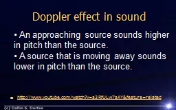
Measuring in Difficult ConditionsDiscussion and guidance on collecting data in the following difficult conditions is provided:Slow FlowFast and (or) Turbulent FlowVertically Stratified Bi-Directional Flow
Shallow Flow
Deep Flow
Vertical Walls
Rough and Irregular Streambeds or Vegetation on the Streambed
Wind
High Sediment LoadSlide28
Critical Data-Quality ProblemsIf a critical data-quality problem is observed during measurement in a transect, the use of that transect may be
terminated. If a transect is not used, the reason should
be documented
in the ADCP
discharge-measurement
field notes
,
and that transect should not be
used
in the computation
of measurement
discharge
.Potential critical data-quality problems can include, but are not limited to the following:Slide29
Estimating Edge DischargeIf an individual edge discharge is more than 5 percent of the total discharge, an alternate method of measuring/estimating the
discharge should be used to check the edge discharge.
An alternate
method could include measuring and (or)
estimating multiple
point velocities and depths in the edge and
computing a
discharge for the edge using the midsection method. If
the edge
discharge measured with the alternate method
agrees with
the ADCP software edge discharge, the ADCP
software edge discharge should be used. If the discharge from the alternative method does not agree with the ADCP software edge
discharge, the more accurate of the two discharges, based on the hydrographer’s judgment, should be used. The alternate method must be documented with the measurement.Slide30
Edge DistanceThe distances from the edge of water to the starting and stopping points of each transect must be measured using a distance- measurement device (such as a laser or optical rangefinder), tagline, or some other accurate measurement device.Slide31
Eddies at EdgeThe velocity used to compute the edge estimate must be representative of the flow in the edge.Slide32
Before Leaving the SiteEvaluate QA/QC Data – ADCP test, compass cal., moving-bedVerify User Input – draft, magvar
, etc.
Evaluate Tabular Data
Evaluate Ship Track and Velocity Vector Plot
Evaluate Velocity Contour Plot
Evaluate Echo Intensity –
Particularly important for
SonTek
Select Proper Extrapolation Methods
Evaluate Discharge Summary –
consistency
Check Measurement? –
Change as much as practicalBackup DataStore ADCP
Appendix F has detailed data review steps and examplesSlide33
In The OfficeAll measurement data should be moved from the field computer or field backup media to an office server within 48 hours of returning from the field
.
Once the measurement has been finalized, it should
be permanently
stored in a manner that would prevent
accidental modification
and (or) deletion
.
All ADCP data, including compass calibration and
ADCP test
results associated with an individual
measurement, should
be stored together in a unique folder.Slide34
Misc.Glossary - addedAppendix A – Updated for newer instruments, including discussion of phased array transducers.
Appendix
B –
Collecting Data in Moving-Bed
Conditions
Updated
with information on using Stationary Moving Bed Analysis (SMBA)
software for
stationary moving-bed tests.
Added
additional details on the importance of compass accuracy when using
loop moving-bed
tests.Added new quality-assurance checks and guidelines for using the loop moving-bed method.
Added potential inaccuracies in VTG-based discharges, particularly for boat speeds less than about 0.8 foot per second.Appendix C – Description of Water-Tracking Modes – Revised to include auto-adaptive capabilities of newer instruments.Appendix
D
– Beam-Alignment Test – Revised to include
RiverSurveyor
M9/S5
and
RiverRay
beam
matrix
descriptions.
Appendix
E
– Forms and Quick-Reference Guides – All forms revised to include
newer equipment and improved with additional information.Appendix F – Measurement Processing Procedure – Completely revised with expanded discussions
for each step.Slide35
Revised Quick SheetsSlide36
Examples for WinRiver and RiverSurveyorSlide37
Air Entrainment - SonTekSlide38
Invalid Bottom Track / Composite TracksSlide39
Read the Report and Use It!!Slide40
Questions