
Functions Clutch Go or limit torque Brake Stop or slow down Backstop Go only one direction Primary function Stop slow or prevent reversal of load in a mechanical system Activation Methods ID: 675332
Download Presentation The PPT/PDF document "Clutches, Brakes, and Backstops" is the property of its rightful owner. Permission is granted to download and print the materials on this web site for personal, non-commercial use only, and to display it on your personal computer provided you do not modify the materials and that you retain all copyright notices contained in the materials. By downloading content from our website, you accept the terms of this agreement.


Slide1
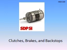
Clutches, Brakes, and Backstops
Slide2
Functions
Clutch – Go (or limit torque)Brake – Stop (or slow down)
Backstop – Go only one direction
Primary function: Stop, slow, or prevent reversal of load in a mechanical systemSlide3
Activation Methods
CentrifugalMechanicalElectrical
Pneumatic
HydraulicSlide4
Applications
Control TorqueDisconnect loadsStarting
Stopping
Prevent load reversal
Tension ControlSlide5
Clutch-like operations by Electrics
Soft startServo drives
Variable speed drives
Positioning systemsSlide6
Application Guide
Brake
Description
Notes
Band
Operates by the action of a fixed belt over a rotating cylindrical surface(drum). Action not harsh.
Band
Drum
Works by bringing curved metal plates, lined with friction material(brake shoes) against an external or internal rotating cylindrical surface.
Drum
Disc
Disc brake consists of a disc rotating between two friction pads. When the pads are forced together under hydraulic, pneumatic, electrical or magnetic action then the disc is very effectively stopped.
Disk
Block/Shoe
Probably the first design of brake based on a shoe/block which is forced against the outside of a rotating wheel. A simple design visible on many old vehicles
Block/Shoe
Fluid
A smooth progressive brake action resulting from rotating plates, or vanes in a retained fluid. When the fluid is prevented from flowing the viscous resistance retards the rotation.
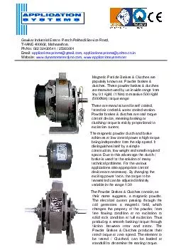
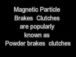
Magnetic
Particle
This type of brake includes a fixed cylindrical enclosure housing a coil wrapped around a fixed cylinder. Within the cylinder is a cylindrical rotor mounted on the rotating shaft. The annulus between the fixed cylinder and the rotor is filled with magnetic particles. If there is no current in the coil the rotor is relatively free to rotate. On applying a current the particles coalesce and prevent relative movement.
Electric
Regenerative
Shafts driven by an electric motor often using regenerative braking. When the power to the motor is removed. The motor effectively becomes a generator driven by the shaft. The shaft is slowed as the kinetic energy is converted into electical energy. The recovered energy is often stored when used in electric vehicles.
Slide7
Selection Criteria
Function of the application
Stopping
Holding
Braking
Slowing
Speed of shaft
Horsepower of prime mover
Torque requirement
Accelerate or Stop time required
Cycle rate
Environmental conditions
Mounting method
Maintenance and servicing required or availableSlide8
General Categories
Positive mechanical engagementSliding or friction engagement
Electrical engagement
Pneumatic or hydraulic engagement
Torque limiting
Centrifugal actuation
One way motion controlSlide9
Positive Engagement Clutches
Relies on engagement of a dog or latch to connect two shaftsNo slippage is possible once engaged
Shock loads are directly transferred.
Tapered surfaces can
permit slow engagement
Tend to become replaced
with better equipment.Slide10
Friction Clutches and Brakes
One surface has friction lining
Surfaces brought into contact by electromagnetic, mechanical, pneumatic, or hydraulic pressure.
Radial engagement
Band
Expanding shoe
Axial engagement
Disc caliper
Plate
CentrifugalSlide11
Friction Materials
Asbestos no longer usedHigh coefficient of friction
Heat resistant
Material Combination
Coefficient of Friction
Temp.(max)
Pressure (Max)
Wet
Dry
Deg.C
MPa
Cast Iron/Cast Iron
0,05
0,15-0,20
300
0,8
Cast Iron/Steel
0,06
0,15-0,20
300
0,8-1,3
Hard Steel/Hard Steel
0,05
0,15-0,20
300
0,7
Wood/Cast Iron-steel
0,16
0,2-0,35
150
0,6
Leather/Cast Iron-steel
0,12-0,15
0,3-0,5
100
0,25
Cork/Cast Iron- Steel
0,15-0,25
0,3-0,5
100
0,1
Felt/Cast Iron- Steel
0,18
0,22
140
0,06
Woven Asbestos/Cast Iron- Steel
0,1-0,2
0,3-0,6
250
0,7
Moulded Asbestos/Cast Iron- Steel
0,08-0,12
0,2-0,5
250
1,0
Impregnated Asbestos/Cast Iron- Steel
0,12
0,32
350
1.0
Carbon-graphite/Cast Iron- Steel
0,05-0,1
0,25
500
2.1
Kelvar/Cast Iron- Steel
0,05-0,1
0,35
325
3,0Slide12
Electrical Clutch and Brake
Electrically activated friction elements
Uses electromagnet to apply force
Magnetic particle
Magnetic particles drawn by coil
Eddy current
?Slide13
Wet and Multiplate
Clutch
Multiple plate clutch
This type of clutch has several driving members interleaved or "stacked" with several driven members. It is used in race cars including F1,
IndyCar
, World Rally and even most club racing, motorcycles, automatic transmissions and in some diesel locomotives with mechanical transmissions. It is also used in some electronically controlled all-wheel drive systems.
Wet vs. dry
A
wet clutch
is immersed in a cooling lubricating fluid which also keeps the surfaces clean and gives smoother performance and longer life. Wet clutches, however, tend to lose some energy to the liquid. Since the surfaces of a wet clutch can be slippery (as with a motorcycle clutch bathed in engine oil), stacking multiple clutch discs can compensate for the lower coefficient of friction and so eliminate slippage under power when fully engaged.Slide14
Pneumatic and hydraulic
Air pressure expands diaphragm or piston to exert force on the friction material.
Springs are used to disengage
Hydraulic actuation can supply higher pressure.Slide15
Torque Limiting Clutches
Provide overload protection
Pressure is applied to friction discs by spring pressure and adjusting nuts.
Intended as an overload protection, not for repetitive startsSlide16
Fluid Clutch
Function to provide soft start, delayed engagement, reduced starting load, and overload protection.
Uses a fluid torque converter.
Consists of an impeller and running vanes in an oil filled housing.
Dry fluid clutch involves the use of shot between the housing and impellers.Slide17
Overrunning clutches
Terms – cam clutch, free-wheeling clutch, backstop,
sprag
clutch, roller ramp clutch, on-way clutch, or single direction clutch.
Allows rotation in one direction and prevents rotation in the opposite direction.Slide18
Overrunning clutch types
Pawl and ratchet
Most primitive
Pawl catches on backside of teeth
Ramp clutch
Spring loaded ball engages outer ring via flat ramp
Sprag
Special shaped locking cams engage inner and outer ring
Garter spring keeps cams centered
Wrap spring clutch
Hubs fit inside spiral wound spring and tighten one direction, slip the other.Slide19
Overrunning Clutch Applications
OverrunningTwo motors (main drive and inching drive) connected to same equipment
Indexing
Backstopping
Safety mechanism
Prevent load reversal
Can mount within gearbox
Holdback
Prevents inclined conveyor from reversingSlide20
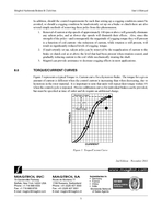
Stopping TorqueSlide21
Stopping TorqueSlide22
Stopping Torque