
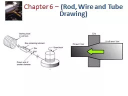
Tube Drawing Drawing can be used to reduce the diameter or wall thickness of seamless tubes and pipes after the initial tubing has been produced by some other process such as extrusion Tube drawing can be carried out either with or without a mandrel ID: 1021991
Download Presentation The PPT/PDF document "Lecture ten Concepts of wire drawing" is the property of its rightful owner. Permission is granted to download and print the materials on this web site for personal, non-commercial use only, and to display it on your personal computer provided you do not modify the materials and that you retain all copyright notices contained in the materials. By downloading content from our website, you accept the terms of this agreement.


1. Lecture tenConcepts of wire drawing
2. Tube Drawing:Drawing can be used to reduce the diameter or wall thickness of seamless tubes and pipes, after the initial tubing has been produced by some other process such as extrusion. Tube drawing can be carried out either with or without a mandrel. The simplest method uses no mandrel and is used for diameter reduction, as in Figure 10.1. The term tube sinking is sometimes applied to this operation. Figure 10.1
3. The problem with tube drawing in which no mandrel is used, as in Figure 10.1, is that it lacks control over the inside diameter and wall thickness of the tube. This is why mandrels of various types are used, two of which are illustrated in Figure 10.2.The first, and Figure 10.2 (a) uses a fixed mandrel attached to a long support bar to establish inside diameter and wall thickness during the operation. Practical limitations on the length of the support bar in this method restrict the length of the tube that can be drawn. The second type, shown in (b), uses a floating plug whose shape is designed so that it finds a ‘‘natural’’ position in the reduction zone of the die. This method removes the limitations on work length present with the fixed mandrel.
4. Figure 10.2 (a) Fixed mandrel (b) Floating plug
5. Advantages of drawing:(1) Close dimensional control.(2) Good surface finish(3) Improved mechanical properties such as strength and hardness.(4) Adaptability to economical batch or mass production. Drawing speeds are as high as 50 m/s for very fine wire. In drawing, reductions in the cross-sectional area per pass range up to about 45 %. Usually, the smaller the initial cross section, the smaller the reduction per pass. Fine wires usually are drawn at 15 to 25% reduction per pass and larger sizes at 20 to 45%. A light reduction (sizing pass) also may be taken on rods to improve their surface finish and dimensional accuracy.
6. Bundle Drawing:Although very fine wire can be produced by drawing, the cost can be high. One method employed to increase productivity is to draw many wires (a hundred or more) simultaneously as a bundle. Bundle drawing produces wires that are somewhat polygonal, rather than round, in cross- section. The wires produced can be as small as 4 µm in diameter and can be made from such materials as stainless steels, titanium, and high-temperature alloys.
7. Drawing Equipment:Bar drawing is accomplished on a machine called a draw bench, consisting of an entry table, die stand (which contains the draw die), carriage, and exit rack. The arrangement is shown in Figure 10.3.The carriage is used to pull the stock through the draw die. It is powered by hydraulic cylinders or motor-driven chains. The die stand is often designed to hold more than one dies, so that several bars can be pulled simultaneously through their respective dies.
8. Figure 10.3
9. Wire drawing is done on continuous drawing machines that consist of multiple draw dies, separated by accumulating drums between the dies, as in Figure 10.4. Each drum, called a capstan, is motor driven to provide the proper pull force to draw the wire stock through the upstream die. It also maintains a modest tension on the wire as it proceeds to the next draw die in the series. Each die provides a certain amount of reduction in the wire, so that the desired total reduction is achieved by the series. Depending on the metal to be processed and the total reduction, annealing of the wire is sometimes required between groups of dies in the series.
10. Figure 10.4 Continuous drawing of wire
11. Draw Dies:Figure 10.5 identifies the features of a typical draw die. Four regions of the die can be distinguished: (1) entry, (2) approach angle, (3) bearing surface (land), and (4) back relief. The entry region is usually a bell-shaped mouth that does not contact the work. Its purpose is to funnel the lubricant into the die and prevent scoring of work and die surfaces.The approach is where the drawing process occurs. It is cone-shaped with an angle (half angle) normally ranging from about 6◦ to 20◦. The proper angle varies according to work material. The bearing surface, or land, determines the size of the final drawn stock. Finally, the back relief is the exit zone. It is provided with a back relief angle (half-angle) of about 30◦. Draw dies are made of tool steels or cemented carbides. Dies for high-speed wire drawing operations frequently use inserts made of diamond (both synthetic and natural) for the wear surfaces
12. Figure 10.5Draw die for drawing of round rod or wire
13. Preparation of the Work:Prior to drawing, the beginning stock must be properly prepared. This involves three steps: (1) annealing, (2) cleaning, and (3) pointing. The purpose of annealing is to increase the ductility of the stock to accept deformation during drawing. As previously mentioned, annealing is sometimes needed between steps in continuous drawing. Cleaning of the stock is required to prevent damage of the work surface and draw die. It involves removal of surface contaminants (e.g., scale and rust) by means of chemical pickling or shot blasting. In some cases, prelubrication of the work surface is accomplished subsequent to cleaning.Pointing involves the reduction in diameter of the starting end of the stock so that it can be inserted through the draw die to start the process. This is usually accomplished by swaging, rolling, or turning. The pointed end of the stock is then gripped by the carriage jaws or other device to initiate the drawing process.
14. Die Material:Die materials for drawing typically are tool Steels and carbides. For hot drawing, cast-steel dies are used because of their high resistance to wear at elevated temperatures. Diamond dies are used for drawing fine wire with diameters ranging from 2 µm to 1.5 mm. They may be made from a single-crystal diamond or in polycrystalline form with diamond particles in a metal matrix (compacts). Because of their very low tensile strength and toughness, carbide and diamond dies typically are used as inserts or nibs, which are supported in a steel casing. Figure (10.6)
15. Figure (10.6) tungsten-carbide die insert in a steel casting. Diamond dies used in drawing thin wire are encased in a similar manner
16. Drawing Defects and Residual Stresses:Typical defects in a drawn rod or wire are similar to those observed in extrusion especially center cracking another major type of defect in drawing is seams, which are longitudinal scratches or folds in the material. Seams may open up during subsequent forming operations (such as upsetting, heading, thread rolling, or bending of the rod or wire), and they can cause serious quality-control problems. Various other surface defects (such as scratches and die marks) also can result from improper selection of the process parameters, poor lubrication, or poor die condition. Because they undergo nonuniform deformation during drawing, cold-drawn products usually have residual stresses. Residual stresses can be significant in causing stress-corrosion cracking of the part over time. Rods and tubes that are not sufficiently straight (or are supplied as coil) can be straightened by passing them through an arrangement of rolls placed at different axe.