/
NASA Thermal Recovery Energy Efficient System (TREES) for Aircraft Exergy Optimization NASA Thermal Recovery Energy Efficient System (TREES) for Aircraft Exergy Optimization

NASA Thermal Recovery Energy Efficient System (TREES) for Aircraft Exergy Optimization - PowerPoint Presentation

anastasia
anastasia . @anastasia
Follow
66 views
Uploaded On 2023-06-25

NASA Thermal Recovery Energy Efficient System (TREES) for Aircraft Exergy Optimization - PPT Presentation

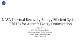
Rodger Dyson NASA Glenn Research Center Exergy Analysis and Design Workshop Wright Patterson Air Force Base April 1718 2019 1 v 2 Prefer technology that improves fuel efficiency reduces emissions ID: 1003301

acoustic heat energy aircraft heat acoustic aircraft energy waste power thermal weight tube efficiency moving core fuel electric wave

Share:

Link:

Embed:

Download Presentation from below link

Download Presentation The PPT/PDF document "NASA Thermal Recovery Energy Efficient S..." is the property of its rightful owner. Permission is granted to download and print the materials on this web site for personal, non-commercial use only, and to display it on your personal computer provided you do not modify the materials and that you retain all copyright notices contained in the materials. By downloading content from our website, you accept the terms of this agreement.


Presentation Transcript

1. NASA Thermal Recovery Energy Efficient System (TREES) for Aircraft Exergy OptimizationRodger DysonNASA Glenn Research CenterExergy Analysis and Design WorkshopWright Patterson Air Force BaseApril 17-18, 20191

2. v2Prefer technology that:improves fuel efficiency, reduces emissions, removes heat from: small core engines, more electric composite aircraft, and high power electric propulsion systemsreduces vehicle massreduces thermal signature for military2Motivation Commercially attractive solution would achieve >15% fuel savingsLow Grade Waste Heat Produced Throughout Insulated Aircraft

3. v 33Thermal ChallengeCurrent proposed solutions include:Ram air HXadds weight and aircraft dragConvective skin cooling HX adds weight, drag, and inefficientDumping heat into fuel limited thermal capacityDumping heat into lubricating oillimited thermal capacityActive cooling adds weight and consumes engine powerPhase change coolingadds weight and limited thermal capacityHeat pipe, pumped multiphase, vapor compressionadds weight and consumes engine power50kW to >800kW of low grade thermal heat trapped within composite aircraft body

4. Electric Aircraft Propulsion Thermal management technology impacts performance and safety certification

5. Energy Quality = Exergy / EnergyHeat Engine Exergy Exchanged: B=Q(1-T0/Tsource) =Q * ηHeat extraction = Exergy DecreaseHeat pumping = Exergy IncreaseTurbineCombustorHeat EnginePowertrainHeat PumpPipe QWQQHeatQQFanW

6. 66Aero-vascular Energy ManagementHuman HeartArtery VeinSkin BloodAircraftTurbofan Acoustic PipeHeat Pipe SkinHelium/GasThree Key Points: Recycle waste energy with heat pumping powered with core waste energy Additive manufactured airframe enables sophisticated heat transport Solid-state thermal control allows transporting energy with no moving partsThermal management comparison of human and aircraft

7. v 7Extract waste energy from turbofan core exhaust and/or SOFC and convert to ducted acoustic waveDeliver no moving part mechanical acoustic energy throughout aircraft in embedded airframe tubesCool and heat pump powertrain and/or more electric components using no moving part thermo-acoustic heat pumpRecycle waste heat with variable conductance heat pipes or additional acoustic tubes.7Basic Principles

8. 8High bypass ratio turbofan (6-12)/turboprop (50-100)Small core and distributed propulsion increases ratio, (e.g., PW1000G ideal)787 with RR Trent 1000 - 10:1Thrust produced mostly by cold bypass airExtract waste energy from coreMinimal impact on overall thrustReduce jet noise V^8~30 MW waste heat availableExtract only 10%, 3 MW -> 1MW acoustic energy availableAlso can extra waste energy from inside fuel cellHeat Energy Extraction

9. Thrust VS. Core ExtractionIn this example, extracting 17.6% of the core enthalpy (3MW) only reduced thrust 0.5%And in fully turboelectric or SOFC applications no thrust is impacted.

10. Heat Pumping10Electric Actuators, Cabin, Cables, Power Electronics, Protection,MachinesMakes more electric parts and powertrain effectively 100% efficientFree Acoustic Mechanical Work InputAll airframe waste is now usefulCryogenic Option2000Win for 50W@50K

11. Acoustic Heat Pump

12. Traveling Energy Wave Basic Principles – Air Molecules Oscillate12By-pass Air Heat ExchangerEngine Core Heat Exchanger Airframe Heat ExchangerHeat Pipe ExchangerStackResonatorResonatorStackBasic principle is to use aircraft engine waste heat to produce a high intensity acoustic wave with no hot moving parts that can be used for power generation or component cooling. The temperature gradient between hot and cold HX efficiently creates the acoustic waves. All energy is delivered through small hollow acoustic tubes.

13. Are there any simple (or complex) equations for estimating the weight and volume requirements relative to the heat conversion to acoustic energy?Basic relationship is 30% of the heat input is converted to acoustic energyPrimary heat transfer limit is surface area but roughly 12kW per 2 inch length of 2” diameter tube with appropriate fin structureInterior copper HX is drilled copper with 90% porosity so estimate per 12kW heat input is a copper mass of (400 g per 12 kW heat input (4 copper HX)) and this will provide 4kW acoustic energy to lift 1kW low grade heat (300K) to provide 5kW of high grade heat at (900K). 800K300K900K330K12 kW Core Heat In8kW Heat Out to Bypass Air5kW Powertrain Heat Out1 kW Cold Sink2”2”

14. 14Cold copper 10X more conductive at 50K, Enables lower voltage, increase specific power, effectively 100% efficient power electronics, cable, motor, protections, actuators, etc.Additively manufactured into airframe enables use of reliable less efficient, flight-weight components for more electric and future electric propulsionAcoustic Recycling Enables Effectively 100% Efficient Flight-Weight Powertrain Since Waste Energy is Reused

15. 15Solid-state Heat Transfer Switching and DistributionSolid-state Heat Transfer Distribution with Variable Conductance Heat Pipes Can control where the heat goes with solid-state no moving parts via acoustic waves and/or variable conductance heat pipes800K300K900K330KHeat Transport OnAcoustic Wave OffSmall InputNo InputHeat Transport OffAcoustic Wave OnNo HeatLow HeatAcoustic Energy Control Method Heat Energy Control Method

16. Benefits of recycled heat pumping16Solid-state (no moving part) energy recycle and distributionlocalized skin heatingfor active lift/drag management, de-icing/anti-icing, powertrain cooling, cabin thermal management, engine recuperation,thrust enhancement in by-pass airmilitary cloaking with thermal skin temperature shiftingSimple solid-state control of heat flow distribution

17. .. lighting the way to a brighter future17TREES Heat Recovery Cycle – LEW-19353-1A thermal management system for an aircraft is provided that includes thermo-acoustic engines that remove and capture waste heat from the aircraft engines, heat pumps powered by the acoustic waves generated from the waste heat that remove and capture electrical component waste heat from electrical components in the aircraft, and hollow tubes disposed in the aircraft configured to propagate mechanical energy to locations throughout the aircraft and to transfer the electrical component waste heat back to the aircraft engines to reduce overall aircraft mass and improve propulsive efficiency.

18. .. lighting the way to a brighter future18Turbine Exit Waste Heat Extraction InstallationRemove waste heat from turbine exhaust with OGV fins located parallel to exhaust flow for flow straightening and high heat transfer rate. Use multiple independent flight-weight no moving part thermo-acoustic power tubes to generate acoustic waves from waste jet exhaust heat

19. 1919Example Wave Generation, Acoustic Tube, and Heat Pump as One UnitNote the power generation, distribution, and heat pump tube can be any length and curved to fit within aircraft. Electric power or cooling can be delivered anywhere in the aircraft without power conductors.

20. 20Energy transport with ducted acoustic waveLight-weight gaseous pressurized helium filled tube delivers energy from turbine to anywhere on aircraft and provides flight-weight structural support.Acoustic heat pumps or generators can provide cooling and/or power using the delivered acoustic energy.

21. Component Cooling or Power Generation21Heat generated from electric motors is conductively removed and rejected to external fins or temperature boosted and the heat is returned to turbofan for cycle efficiency improvement.Overall system is flight-weight, efficient, structural, flexible, maintenance-free, and has no hot moving parts while enabling full vehicle heat rejection through nozzle.

22. 22Heat Recycling and Nozzle RejectionSimilar technology for spacecraft because of the reliability, specific power, efficiency, and no maintenance.  Only technology option that has no hot moving parts, 52% Carnot WHR power efficiency and 44% Carnot heat pump efficiency, and is bi-directional in that it can both generate its own power and act as a heat pump all in a single contiguous hollow tube that can easily be distributed throughout the aircraft with minimal mass.  The key is to optimize the system as a traveling wave device and the tools for doing that have only recently become available.All waste heat recycled and rejected out nozzle.

23. 2323Net System Cycle Benefit (1.6% - 16%)Example idealized net benefit calculation (16% fuel savings):24MW thrust for Boeing 737 using a pair of CFM56 engines operating at 50% efficiency produce ~12MW of waste heat at 450C out the nozzle with 25C by-pass fan air surrounding it52% of Carnot Efficiency for WHR, approximately 4MW of mechanical acoustic energy available 1MW of low-grade 100C distributed heat sources throughout the insulated composite aircraft requires ~3MW of mechanical input to raise to 600C44% of Carnot Efficiency for heat pump, heat pipes return the 600C 4MW of energy to combustor Best case idealized scenario achieves fuel savings of 16% while providing a flight-weight method for managing the aircraft’s heat sources without adding aircraft drag and weight.  All heat is used in the most optimal way and ultimately rejected out the nozzle instead of through the aircraft body. Drop-in Solution with Conservative Assumptions (1.6% fuel savings):Note that the outlet guide vanes as currently installed in the CFM56 could act as WHR fins extracting about 10% of the nozzle waste heat so that 100kW of low-grade distributed 100C aircraft heat sources could be returned to the combustor as 400kW, 600C useful heat resulting in a potential fuel savings of 1.6%.  This changes aircraft thermal management from being a burden on aircraft performance to an asset.

24. 24Key Features Include:Turbofan and/or fuel cell waste heat is used to generate ducted acoustic waves that then drive distributed acoustic heat pumps and/or generate power throughout the aircraft.Low grade powertrain waste heat is converted into high grade recycled heat and returned to the engine combustor via heat pipes or additional acoustic tubesPressurized acoustic and heat pipe tubes can be directly integrated into the airframe to provide structure support with mass reduction.Fuel savings of 16% are estimated with a purpose-built systemAll aircraft heat is rejected through engine nozzle, by-pass stream, outer mold line de-ice Non-provisional Patent Filed With Priority Date November 6, 2015.24ConclusionTREES changes aircraft thermal management from being a necessary burden on aircraft performance to a desirable asset. It improves the engine performance by recycling waste heat and ultimately rejecting all collected aircraft heat out through the engine nozzle.

25. Appendix: Basic Theory

26. PV Power and Waves

27. Alpha Stage PhysicscoldhotcoldrejectorregeneratoracceptorThermal buffer tube (TBT)Simplified physical appearance

28. Thermodynamic CyclecompressionWcmpQrejexpansionWexpQaccGas displacement boundaryDisplacement, Pdisplacement, P

29. Thermal Buffer Tube/Pulse TubecoldhotTBT Isolates hot from cold parts Transmits PV power, like a compliant displacer Adiabatic (ideally) Except for jets, streaming, turbulence, etc.

30. Two stage cascadeWcmpWexpStage 1Stage 2Physical transducer boundaryGas Coupling

31. PV PhasingStage 1Stage 2P1U1P1U1P1U1P1U1 P1 phasors everywhere nearly constant U1 phasors progressively lag due to volume (compliance) Ideally, P1 and U1 in phase in regenerators Gas inertia (inertance) can be used to counter U1 lag E.g. Swift inter-stage inertance tube (see reference 4)

32. End Transducer OptionsHigh Impedance (Piezo or magnetorestrictive)Low Impedance (Moving Magnet actuator)P1 high, U1 lowP1 low, U1 highImpedance is P1 / U1

33. High Impedance Matching Quarter-wave solid resonator converts low stirling impedance to high transducer impedance Low Dissipation losses critical Coef of restitution > 0.9999 Three-dimensional effects? Piezo transducers prefer higher frequency than stirling thermodynamics allowsImpedancematcherImpedancematcherP1u1

34. Electro-acoustic transducer (size & weight versus capacity)?Not required since can use standing wave driver (see Swift ref. 1)Key Point is the type and size of driver can be very small because of thermo-acoustic amplification from multiple stages in series. Next series of slides explains this.And note that TREES uses a traveling wave without the loop shown in F1. b) by using an RC Helmholtz terminator.

35. Basic Turbofan Model with Core Extraction

36. What are the pressure and duct size relationship to acoustic/thermal energy transfer?Pressure = Pm+ Apc * Cos( omega * t) + Aps * Sin (omega * t) [Pa]Mass flow rate = Mm+ Amc * Cos( omega * t) + Ams * Sin(omega * t) [kg/s]Acoustic Power = 0.5 * (Apc * Amc + Aps * Ams)/RhoRho = Gas densityMass flow rate = Rho U AVolume Flow Rate = U ANote pressure and volume flow rate are oscillating – maximizing pressure swing amplitude and frequency increases specific power

37. Does acoustic energy flow suffer frictional type pressure drop, similar to a fluid pressure drop?Very specific example for simple 7 m length tube:32kW Incoming acoustic wave in a 4.72 cm diameter tube will see a 26% power drop after 7 m of travel. Mean pressure is 3 Mpa and 84 Hz. This is not optimized. Can recover using narrowing tube approach described in page 9 and ref. 4. But gives an idea of potential losses with simple non-tapered very narrow tubes (about 1% per foot).And the main point is this acoustic energy is free from the jet core

38. What percentage of the Carnot cycle efficiency are you seeing in lab testing?52% of Carnot cycle efficiency in converting 850C heat input to mechanical acoustic energy outputAnd for converting mechanical acoustic energy to high grade heat flux it depends on heat load:

39. Lip anti-icing 1MW acoustic energy could be delivered to lip area to pump up free-stream air from -30C to 300C. Effectively can provide continuous 2MW of hot air at 300C.This is sufficient for anti-ice of entire aircraft without using bleed air or electric power.

40. ReferencesSwift. JASA, 114(4), 2003 – Fig. 1cKim, IECEC 2006-4199Timmer, JASA, 143, 841, 2018Swift, LA-UR 11, 2011Al-Khalil, J. Propulsion, 89-0759Gelder, NACA TN 2866, 1953