
FLAME CURRENT MEASUREMENT Flame current of the device can be measured using a standard microammeter by simply touching the meter leads to the 2 PIN labeled FC as shown in Figure 2 Flame current must ID: 863409
Download Pdf The PPT/PDF document "BASO Gas Products" is the property of its rightful owner. Permission is granted to download and print the materials on this web site for personal, non-commercial use only, and to display it on your personal computer provided you do not modify the materials and that you retain all copyright notices contained in the materials. By downloading content from our website, you accept the terms of this agreement.


1 BASO Gas Products
BASO Gas Products Page 8 Part No. BASO-INS-E34, Rev. C FLAME CURRENT MEASUREMENT Flame current of the device can be measured using a standard micro-ammeter by simply touching the meter leads to the 2 PIN labeled FC, as shown in Figure 2. Flame current must be measured with pilot valve lit but no main gas flowing. Set meter to DC µAmp scale. Make sure meter leads are positioned correctly [+/-]. Recommended Minimum Pilot Only Flame Sense Current of 0.8 µAmp DC. Figure 2: Microammeter connection. RED (+) BLACK (-) 2 year warranty BASO Gas Products Page 7 Part No. BASO-INS-E34, Rev. C Symptom Possible Cause1. No power up Faulty 24 VAC wiring Thermostat or transformer Faulty control 2. Control LED is blinking RED Determine error code, refer to error codes (TABLE 5), also refer to the troubleshooting flow chart in the installation instructions 3. No spark during Trial for Ignition (TFI) time Faulty spark electrode wiring Spark g
2 ap too wide Faulty control 4. Pilot/Burn
ap too wide Faulty control 4. Pilot/Burner does not light during trial for ignition time Faulty valve wiring Bad Gas Valve Faulty control 5. Pilot/Burner lights but Gas Valve turns off after TFI Weak flame, Flame not in contact with the spark electrode or flame sensor. Check that Flame Sensor tip is in the flame. For proper sensing the rod tip must be 3/8 (10mm) to 1/2 (13 mm) in the flame. See figure 1. Dirty or corroded flame sensor Faulty flame sensor wiring Poor burner ground For more information on BASO ignitions and other products, plus complete installation instructions, please visit us at www.baso.com . Figure 1: Proper Flame Sensor position FLAME TOO LOW FLAME TOO HIGH BASO Gas Products Page 6 Part No. BASO-INS-E34, Rev. C LED STATUS AND TROUBLESHOOTING The ignition control has a multi-colored (GREEN, ORANGE, and RED) LED which will flash different colors and codes to show status of the ignition, and will help troubleshoot the control. Table 3: GREEN LED Indications of Normal Ope
3 ration Flash Indication On ½ sec, Off 4-
ration Flash Indication On ½ sec, Off 4-½ sec Waiting for Call for Heat On ½ sec, Off ½ sec Pre-purge, Inter-purge, Post-purge On ¼ sec, Off ¼ sec Trial for Ignition (TFI) On Solid RUN (Flame, Pilot/Main valves on) Table 4: ORANGE LED Indications Flash Indication ERROR Type On ½ sec, Off 4-½ sec Retry Standby On ½ sec, Off ½ sec Flame present Standby On ½ sec, Off ½ sec Pressure present Standby Table 5: RED LED Indications of ERROR Codes (100% Lockout). Flash Error Indications ERROR Type 1 flash No flame in trial time 100% Lockout 2 flashes Flame sense stuck 100% Lockout 3 flashes Valve/Pilot relay circuit 100% Lockout 4 flashes MV/Inducer circuit 100% Lockout 5 flashes Rollout error 100% Lockout 6 flashes Pressure switch 100% Lockout 7 flashes Repetitive flame loss 100% Lockout 8 or 9 flashes Internal control 100% Lockout Solid On Line voltage/Freq. Standby Note: 1 second pause after each flash code. BASO Gas Products Page 5 Part No. BASO-INS-E34, Rev. C Figure 2: Wiring for 2 Rod Flame S
4 ense used for Remote (External) Se Se")
ense used for Remote (External) Sense See notes on rollout switch and vent damper jumper plug on previous page. Warning: Risk of explosion or fire. Do not install the control in an area that is exposed to water (ex. dripping, spraying or rain). Do not use the control if it has been exposed to water. Exposure to water may cause a malfunction and can lead to an explosion, which can lead to severe personal injury or death. FC- + 24V INT SENSE HIGH TEMPLIMIT MV/PVCOMBRNGNDALM24V GNDBRN GNDTH-WDIP SWITCHSPARKTHERMOSTAT PILOT BURNER COMBINATIONGAS VALVE24 VACCLASS 2TRANSFORMERL1 (HOT)L2 (NEU) CHASSIS OR FRAMEGROUND DAMPERRESISTIVE WIREALARMROLLOUTSWITCH(OPTIONAL) BASO Gas Products Page 4 Part No. BASO-INS-E34, Rev. C Figure 1: Wiring for 1 Rod Flame Sense used for Local (Internal) Sense A rollout switch (a normally closed set of contacts) is positioned to detect flames rolling out of the combustion chamber. If rollout occurs, the switch contacts open and the control immediately goe
5 s into a lockout condition. The main and
s into a lockout condition. The main and pilot valves also close so that the system is not allowed to function. A vent damper jumper plug that jumpers pins 2 and 3 of the damper connec-tion, is supplied with controls ordered with a vent damper system. The con-trol will operate normally with this plug in place, remove this plug to connect a vent damper. Once a vent damper has been connected to the control, and the power cycled, an internal fuse will blow* and the control can then only used with a vent damper connected. *Note: it is normal to hear a defined pop when the fuse blows. FC- + 24V INT SENSE HIGH TEMPLIMIT MV/PVCOMBRNGNDALM24V GNDBRN GNDTH-WDIP SWITCHSPARKTHERMOSTAT PILOT BURNER COMBINATIONGAS VALVE 24 VACCLASS 2TRANSFORMERL1 (HOT)L2 (NEU) CHASSIS OR FRAMEGROUND DAMPERRESISTIVE WIREALARMROLLOUTSWITCH(OPTIONAL) BASO Gas Products Page 3 Part No. BASO-INS-E34, Rev. C WIRINGTable 1: Typical Wiring Connections. Term. TypeDescriptionMounting TabBurner Ground connection*Flame Current meas
6 uring for microammeter probes in µAmp DC
uring for microammeter probes in µAmp DC¼ male QCCommon side (return) of transformer connection¼ male QCMain Valve connectionMV/PV ¼ male QCGas Valve common terminal¼ male QCPilot Valve connection¼ male QCAlarm Signal¼ male QC24V Power Transformer connection¼ male QCThermostat Call for Heat signal¼ male QCRoll-out connectionkeyed plugVent Damper connection. Leave Vent Damper Jumper Plug installed if not a Vent Damper system¼ male QCFor dual rod (remote/external) flame sensing, connect the flame sense wire from burner/igniter to this terminalINT¼ male QCFor single rod (local/internal) sensing, there will be no connection .¼ male QCHigh voltage sparking electrodeDIP SWITCH N/ANot applicable on fixed timing ignitions. * If the existing system uses a burner ground wire, this can be attached to the 24V GND / BRN GND terminal using the supplied dual spade connector, or otherwise connected to the burner ground mounting tab. BASO Gas Products Page 2 Part No. BASO-INS-E34, Rev. C AGENCY C
7 ERTIFICATIONS: UL 60370-1, UL 60730-2-5
ERTIFICATIONS: UL 60370-1, UL 60730-2-5 File:M2926 Software Conforms to UL 60730 Requirement Component Recognized System (US & Canada) Input VoltageControl: 24 VAC (18-30VAC) 50/60 HzInput Current0.3 A nominal + valvesGas Valve Contact Rating2A Pilot and 2A Main @ 24 VACAlarm Output 2A @ 24 VAC Operating Temperature-40 to 176°F (-40 to 80°C)Flame Detection MeansFlame RectificationFlame Detection TypeLocal/Internal or Remote/ExternalMinimum Flame Current0.07 microamperesFlame Failure Response Time1.0 second maximumIgnition SourceHigh voltage spark, capacitive dischargeMaximum Spark Gap0.2 in. (5.1 mm)High Voltage Cable48 in. (1219mm) max., rated 15kV min. (Resistive recommended)Flame Sense Cable48 in. (1219mm) max (Shielded recommended)30 sparks/secondHumidity0% to 95% RH (non-condensing)Gas TypesNatural, LP, or ManufacturedTrials Before 100% Shutoff*Preset 1, 3, Cont.Trial for Ignition Time *Preset 4, 8, 15, 30, 60, 90 secondsPre-Purge Time *Preset 0, 15, 30 or 45 secondsInter-Purge Time *Preset 0, 15, 30, 300, 360 secondsRetry Delay Period *Preset 0
8 , 5, or 60 minutesLockout RecoveryPower
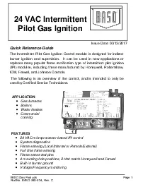
, 5, or 60 minutesLockout RecoveryPower cycle / Thermostat (TH-W) cycle * For custom timings, contact BASO Gas Products. BASO Gas Products Page 1 Part No. BASO-INS-E34, Rev. C 24 VAC Intermittent Quick Reference Guide The Intermittent Pilot Gas Ignition Control module is designed for indirect burner ignition and supervision. It can be used in new applications or replaces many popular flame rectification type of intermittent pilot ignition (IPI) modules, including those manufactured by Honeywell, Robertshaw, ICM, Fenwal, and Johnson Controls. The following is an overview of the control, and is intended to only be used by Certified Service Technicians. APPLICATION Gas furnaces Water heaters cooking FEATURES 24 VAC microprocessor based IPI control System diagnostics Flame sensing (Local/Internal or Remote/External) Full time flame sensing Flame sense test pins 4 mounting hole positions, 2 that match Honeywell and Fenwal Built-in burner ground Voltage/Frequency monitoring Issue Date: 03/13/2017