
thema 3 Second Wuhu Bridge Design Overall The approach bridges from movement joint to movement joint Approach Bridge of Second Wuhu Bridge 3 The approach bridges of the Second Wuhu Bridge under con ID: 823413
Download Pdf The PPT/PDF document "Approach Bridge of Second Wuhu Bridge" is the property of its rightful owner. Permission is granted to download and print the materials on this web site for personal, non-commercial use only, and to display it on your personal computer provided you do not modify the materials and that you retain all copyright notices contained in the materials. By downloading content from our website, you accept the terms of this agreement.


themaApproach Bridge of Second Wuhu Bri
themaApproach Bridge of Second Wuhu Bridge3Second Wuhu BridgeDesign OverallThe approach bridges (from movement joint to movement joint) Approach Bridge of Second Wuhu Bridge3The approach bridges of the Second Wuhu Bridge under construction Deviator and diaphragm section details [m]Cross sectionThe cross section is designed to be a single-cell arrangement with side wings (fig. 3). The elements are made with C50 concrete. Constant depth is designed for each kind of bridge. The height for 55 m span is 3.25 m and 2.50 m for 40 m span. The height for 30 m span of both six lanes and four lanes are 2.00 m. The deck width of box girders of six lanes bridge is 16.25 m and 12.50 m for the four lanes bridge. Due to the application of fully externally pre-stressed tendons, no pre-stressed tendons are arranged in the web and flanges. The dimensions are optimized to reduce the segment weight. The minimum thickness of top slab and bottom slab is 220 mm and 200 mm respectively. The web is design to have various thick-ness and the thinnest part is 330 mm. Optimizations of the section dimensions helps reducing necessary lifting equipment capacity. The same parts of sections for four kinds of bridges are designed to be as much as possible similar to reduce the complexity of precast forms.For four lanes bridge section, there are no transverse rib both inside and outside the box girder. For six lanes bridges, there are no transverse ribs inside the box due to its complex inner form, while transverse ribs are designed under both sides of the cantilevering deck to achieve the very long side wings. The rib section is inverted trapezoid for mold releasing. Segment DivisionAll approach bridges are designed to have only four types of box segment: standa
rd segment (A), deviator segment (B), st
rd segment (A), deviator segment (B), strengthening segment (C) and diaphragm segment (D) (fig. 2 and fig. 4). The length for the first three types of segments is 3.00 m. Considering the lifting capacity, the length of diaphragm segment is set to be 1.40 m. In this way, the heaviest weight of diaphragm segment is controlled to be within 100 t, due to the consideration of both lifting and transport machines capacity, as well as the cost of enhancing the temporary erection road.Deviator segment is the place where tendons steer. The only difference for deviator segment from standard one is two more deviator blocks at inner box. Strengthening segment and diaphragm segment are designed for the anchorage of tendons. The huge and concentrated force is a big challenge for structural safety at these two types segments. Both theoretical calculation and FEM simulation have been applied to optimize the shape and ensure safety and durability.For all approach bridges, the span at the end contains several standard segments, two deviator segments, two diaphragm segment and one strengthening segment (fig. 2). The span in the middle contains several standard segments, two deviator segments and two diaphragm segment. In total, there are 20032 segments for the whole approach bridge project.Ke HU, Zuqiao MAAnhui Transportation Holding Group Co.Xuefei SHI, Xin RUANTongji UniversitythemaApproach Bridge of Second Wuhu Bridge3Ending spans of approach bridges with their segment divisionStandard section details [m]External tendon profileStorage of the segmentsConstruction site at the shore of the Yangtze Rivertendons to provide no more than 10 MPa compression stress in the concrete deck to make sure the concrete slab will not crack under traffic load i
n the operation period.JointEpoxy is u
n the operation period.JointEpoxy is used for the joint between each segment. The material itself has a minimum compression strength of 60-70 MPa and serves a good function for segment connection. Although it takes time to daub when erection on site, it helps to enhance the durability of the joint. Each span has a 150 mm concrete wet joint as well. The concrete grade is the same as the precast elements. It is cast on site in case of segment cumulative misalignment.PrestressThe approach bridges are fully externally prestressed in longi-tudinal direction; the maximum prestressing stress in the girder is about 12 MPa. For each kind of bridge, there are eight tendons in one span. They steer at the same longitudinal position and are anchored at a different height of anchorage block (fig. 5). For approach bridges with 6 × 30 m span arrangement, each tendon is composed with 25 strands of high strength steel strand for end span and 26 strands for middle span. The nominal area of each strand is 139 mm and the design yielding stress of strand steel is 1860 MPa.For the girder top slab, there are transverse post-tensioned 3Approach Bridge of Second Wuhu Bridge3compared to previous similar bridge construction projects in China considering both the time and staff savings. ConclusionThe approach bridge of the Second Bridge of Wuhu Yangtze River Highway Bridge is a good practice of industrialized construction. The whole project is scheduled to be finished in 2017. Application of precast segmental externally prestressed concrete bridge makes the design standard. Repetitive construction procedures reduce costs and construction time about 10 to 20 percent compared to traditional cast-in-place concrete girder scheme. Factory production enhances qual
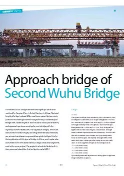
ity and minor site disruption. The proje
ity and minor site disruption. The project is a model for large-scale infrastructure construction (photo 7). ConstructionPrecastThe 20032 segments are cast in four casting yards with 90 cast cells. Steel rebar is assembled first at steel jigs in the cast yards. The details of steel cages are simulated accurately through CAD and the assembling sequence is optimized to ensure quality and speed of work. Then the segments are cast in the precast cells through short-line method a new segment is match-cast against the preceding segment.A cycle time of one standard segment per day per casting cell can be achieved by steam curing. TransportationA cast segment is lifted and transported to the storage yard through gantry crane. Due to the time schedule and site constraints, double layer stacking is applied and the storage sequence is carefully planned to avoid additional lifting work (photo 6). The storage area is close to the bridge and the segments are transported within the right-of-way of the approach project.ErectionSpan-by span erection is applied as the approach bridge construction method (photo 1). Both overhead gantry and underslung gantry are used in the project. A cycle time of five days per span can be achieved by overhead gantry, and 4 to 4.5 days per span by underslung gantry.Internet platformTo ensure the efficiency and accuracy of the construction, an internet platform has developed. The platform stores and delivers all the information and is involved in both segment precast and erection. With the help of the internet platform, only one engi-neer needs to be prepared for data handling and the response time of checking and providing precast or erection coordinate is within 10 min. The work efficiency increased three times as