
AEH 1201 6108 magnetic coupling PUMP TECHNOLOGY AEH P II 13 133413255 5 01 0 2 201 7 TECHNICAL DATA output max 35 m ID: 831086
Download Pdf The PPT/PDF document "Side Channel Pumps" is the property of its rightful owner. Permission is granted to download and print the materials on this web site for personal, non-commercial use only, and to display it on your personal computer provided you do not modify the materials and that you retain all copyright notices contained in the materials. By downloading content from our website, you accept the terms of this agreement.


Side Channel Pumps AEH 1201 ... 61
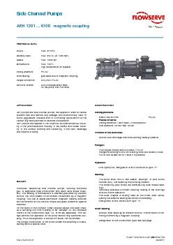
Side Channel Pumps AEH 1201 ... 6108 magnetic coupling PUMP TECHNOLOGY AEH P II / 13 133.41325.55.01 02/2017 TECHNICAL DATA output: max. 35 m³/h delivery head: max. 354 m (at 1450 rpm) speed: max. 1800 rpm temperature: max. 180°C high temperature on request casing pressure: PN 40 shaft sealing: glandless due to magnetic coupling flange connection: DIN 2501 PN 40 sence of rotation: anti-clockwise when seen on the pump from the drive APPLICATION AEH pumps are side channel pumps, are applied in order to handle problem-free and without any leakage and economically clear or turbid, aggressive, valuable toxic or ill-smelling liquids which do not contain any solid particles or abrasive components. AEH pumps are applied in the chemical and petrochemical indus-try, in the pharmaceutical industry, in the plastic and rubber indus-try, in the surface finishing and hardening, in the food, beverage and tobacco industry. BAUART Horizontal, selfpriming side channel pumps, handling entrained gas, of segmental type construction with open vane wheel impel-lers. The sealing to atmosphere is effected glandless by isolation shroud; the drive power is transmitted contactless by a magnetic coupling. The use of stable permanent magnetic material ensures the transmisson of the nominal torque and given protection against overload.. On the basis of the compact close coupled design has been creat-ed a pumping unit that is easily to be installed. All IEC standard motors of the construction type IM B 35 are applicable. This de-sign permits the operation of the pump without any additional cou-pling. Thus the alignment, a source of trouble, can be omitted. The simple construction of the pump allows the assembly or disas-sembly without special tools. CONSTRUCTION Casing pressure: Sizes 1200 to 6100: PN 40; Please observe: Casing pressure = zero head + inlet pressure Test pressure 52 bar resp. 33 bar Position of the branches: Suction and discharge branches pointing radially upwards. Flanges: The flanges comply with DIN 2535 / PN 40 Flanges according to DIN 2512 with groove and bored to ANSI 150 or 300 as well as BS Table F is possible. Hydraulic: First hydraulics, designation of this construction type: A⢠Bearing: The pump shaft runs in two sleeve bearings of pure silicon carbide (SiC), lubricated by the pumping medium. The remaining axial forces are absorbed by
axial sleeve bear-ings. Optionally
axial sleeve bear-ings. Optionally available a friction reducing coating of the bushings to avoid critical operation. The outer magnet is directly fixed on the motor shaft conse-quently the external bearing becomes unnecessary. Designation of this construction type: â¢F Shaft sealing: Without shaft seals by an isolation shroud. Transmission of the driving moment by a magnetic coupling. Designation of this construction type: see last page. 2 Material design: MATERIAL DESIGN Pos. Components 1A 1B 1F 4B 4F 10.60 10.70 10.80 10.90 11.40 11.41 suction casing discharge casing intermediate piece GGG 40.3 (0.7043) 1.4408 21.00 shaft 1.4021 1.4462 23.50 vane wheel impeller 2.0550 1.4517 PAEK 1.4517 PAEK 0242 bearing bush from 5-stages: special carbon special carbon 31.40 52.90 52.91 54.00 54.01 thrust bearing radial bearing radial bearing SiC 34.60 stool GG 25 (0.6025) or 1.0570 81.70 sealing shroud Hastelloy C4 or ZrO2 81.71 flange for can 1.0570 84.71 internal magnet 1.4571/SmCo 84.72 external magnet 1.0570/SmCo 84.80 driving flange 1.0570 Casing sealing: The casing sealing is made by soft Teflon and O-ring PTFE. Designation of this construction type: 4 Drive: By commercial three-phase A.C. motors, construction type IM B35. The selection is depending on the power consumption of the hydraulics, taking into consideration the density and viscosity of the pumping medium. For the motor rating the eddy current losses are to be added to the pump performance. Motors controlled by frequency converters are admissible. The motors and magnetic couplings indicated in the delivery programme are select-ed for a mains frequency of max. 50 Hz and are applicable for watery liquids. In case of differing speeds other magnetic dipole moments are necessary for the couplings. It is recommendable to check the selection with Sterling SIHI. Position: Usually the pump units are installed horizontally. The operation with vertically installed pump units is possible, but should be made only in con-sultation with Sterling SIHI because of the special instructions for starting-up, the support and thermal load of the drive motor. General remarks: The following pump series with magnetic couplings are available: Side channel pump with NPSH inducer stage: Series CEHB with axial inlet and low NPSH Volute casing pumps: Series CBMD volute casing pump
as per DIN EN 22858 bearing bracket des
as per DIN EN 22858 bearing bracket design Series CBED volute casing pump as per DIN EN 22858 close coupled construction Series ZLKD volute casing pump close coupled construction - branches as per DIN 24255 / EN 733 Series ZLID inline pump For lower delivery heads: Series AKLA /AKVA single-stage inline side channel pump Technical documentation on these programmes is available on request. 3 Sectional drawing and nomenclature 10.60 suction casing 23.50 vane wheel impeller 54.00 bearing bush 10.70 discharge casing 31.40 thrust bearing 81.70 isolation shroud 10.80 intermediate piece 34.60 stool 81.71 flange of can 10.90, 10.91 suction piece 35.50 bearing bracket casing 84.71 Iinterior magnet 11.40, 11.41 discharge piece 38.10 bearing carrier 84.72 exterior magnet 21.00 shaft 52.51 spacer ring 84.80 driving flange 23.10 impeller 52.90, 52.91 sleeve 90.60 shaft screw FUNCTION Partial flow: For the cooling of the isolation shroud, heated up by eddy currents, a partial flow is derived which at the same time serves as lubricant for the ceramic sleeve bearings. The partial flow flows through two longitudinal bores in the discharge casing into the isolation shroud and is led back through the hollow bored shaft and the balance bores of the rear vane wheel impeller to its suction side. By the pumping capability of the inner magnet, inside the isolation shroud a circulation flow is created which flows through the longitudinal bores of the inner magnet towards the bottom of the isolation shroud and in the gap between inner magnet and isolation shroud back to the front side of the inner magnet. This circulation flow is nearly independent of the operating point of the pump. Conse-quently the cooling of the isolation shroud is guaranteed over the entire characteristic. By the pumping capability of the lubricating grooves in the thrust bearing disk a further flow is created through the bearing gap of the radial bearing over the thrust bearing towards the longitudinal bores of the inner magnet. Thus, also independent of the operating point of the pump, the lubrication of the bearings is guaranteed. Bearing: The SiC bushings are clamped axially on the shaft. The material combination secures that the clamping power is maintained also in case of high temperatures. The sleeve at suction side is secured on the shaft by a shoulder stud. TH stationary bearing inserts are screwed to the discharge casing or presse
d into the bearing bracket casing. Al
d into the bearing bracket casing. Alternatively bearings coated with adamantine car-bon are available. Hereby are considerably reduced the coefficients of friction during dry operation and danger to the pump can be pre-vented. This coating is applicable up to 250°C. Safety: The magnetic bell is directly fixed on the motor shaft. The load on the bearings resulting from this is relatively slight and therefore a damage to the bearings very improbable. In order to protect the iso-lation shroud against internal or external damages by rotating parts, a stationary seat is installed in the stool and at the bearing insert. The distance from the rotors is smaller than that of the rotors from the isolation shroud. In order to obtain double leakproofness the application of fanless motors which withstand flooding, is possible. Then the sealed stool chamber serves to control the function of the isolation shroud. The pump has to be run with a motor load detector. It protects the machine against dry operation and operation beyond the range of the characteristic curves. VARIANTS Pumps with heating or cooling chambers for the handling of smeltings or boiling media also are available. For such cases special heating stages, instead of normal stages, are installed in the pump and thus offering the heating or cooling by means of liquid or vapour. 4 Characteristic curves 5 Characteristic curves 6 Characteristic curves 7 Dimension table ut : connection for temperatur probe G¼ flanges acc. to DIN 2501 PN 40 DNA/E 20 32 40 50 65 D 115 140 154 165 190 k 75 100 110 125 145 d1 x number 14 X 4 18 x 4 18 x 4 18 x 4 18 x 8 flanges acc. to ANSI 300 RF DNA/E 20 32 40 50 65 D 115 140 154 165 190 k 82,5 98,4 114,3 127 149,2 d1 x number 19 x 4 19 x 4 22,2 x 4 19 x 8 22,2 x 8 Dimensions of the motor size nominal power D1 h m3 m5 n3* n4 o1* s1* s2* w* weight IP54 resp. EExde EExe mm abt. kg 80A 0,55 0,55 200 80 50 100 151 125 229 8,5 15 121 8,3 80B 0,75 0,75 200 80 50 100 151 125 229 8,5 15 121 10 90 S 1,1 1,0 200 90 56 100 180 140 250 10,5 - 167 14 90 L 1,5 1,35 200 90 56 125 180 140 275 10,5 - 167 18 100 L 1 2,2 2,0 250 100 63 140 205 160 323 12 - 175 23 100 L 2 3,0 2,5 250
100 63 140 205 160 323 12
100 63 140 205 160 323 12 - 175 25 112 M 4,0 3,6 250 112 70 140 230 190 329 12 18 191 38 132 S 5,5 5,0 300 132 89 140 266 216 361 12 18 213 59 132 M 7,5 6,8 300 132 89 178 266 216 399 12 18 213 69 160 M 11,0 10,0 350 160 108 210 310 254 470 15 22 245 108 160 L 15,0 13,5 350 160 108 254 310 254 514 15 22 245 130 180 M 18,5 15,0 350 180 121 241 345 279 536 15 25 280 162 180 L 22,0 17,5 350 180 121 279 345 279 574 15 25 280 176 200 L 30,0 24,0 400 200 133 305 400 318 656 20 26 302 254 225 S 37,0 30,0 450 225 149 286 450 356 678 20 26 353 305 225 M 45,0 36,0 450 225 149 311 450 356 703 20 26 353 335 250 M 55,0 44,0 550 250 168 349 505 406 790 25 36 406 425 * dimension dependent on motor make 8 Dimensions of the pump size torque of the magnetic weight of the IP 54 EExe II T3 coupling DNA DNE a a1 a2 b c D2 e e1 e2 e3 f h1 h2 h3 m1* m2* n1 n2 s pump kW kW mm abt. kg 1201 0,55 0,55 46 0,75 0,75 585 555 0,75 0,75 120 178 228 1202 1,1 1 K 227 593 561 51 1,5 1,35 618 586 0,75 0,75 619 589 1203 1,1 1 154 212 262 627 595 62 1,5 1,35 P 652 620 2,2 2 237 684 652 1,1 - K 227 661 629 1204 1,5 1,35 P 188 246 296 686 654 65 2,2 2 237 718 686 3 2,5 V 1,5 1,35 227 720 688 - 2 1205 2,2 - 20 20 222 280 330 32 10 182 44 17 34 17 237 100 100 100 752 720 140 105 13 67 3 2,5
-
- 3,6 762 727 - 1,35 227 754 722 - 2 1206 2,2 - on 256 314 364 786 754 70 3 2,5 request 4 3,6 796 761 - 2 1207 2,2 - 290 348 398 237 820 788 73 3 2,5 4 3,6 830 795 2,2 2 854 822 1208 3 2,5 324 382 432 76 4 3,6 864 829 - 5 257 908 868 size torque of the magnetic weightof the IP 54 EExe II T3 coupling DNA DNE a a1 a2 b c D2 e e1 e2 e3 f h1 h2 h3 m1* m2* n1 n2 s pump kW kW mm abt. kg 3101 1,1 1 295 696 664 3601 1,5 1,35 721 689 122 2,2 2 305 753 721 1,5 1,35 146 213 270 295 721 689 3102 2,2 2 753 721 130 3602 3 2,5 T 305 4 3,6 763 728 2,2 2 793 761 3103 3 2,5 305 3603 4 3,6 186 253 310 803 768 138 - 5 325 847 807 5,5 - W 3 2,5 305 833 801 - 3,6 T 843 808 3104 - 5 226 293 350 325 887 847 142 3604 4 - W 305 843 808 5,5 - 325 887 847 - 6,8 Z 925 885
3 - 3
3 - 305 873 841 - 3,6 883 848 3105 - 5 32 32 35 12 260 42 17 50 17 325 112 132 132 927 887 170 135 13 3605 4 - 266 333 390 305 883 848 146 5,5 - 927 887 - 6,8 325 965 925 7,5 - - 3,6 305 923 888 4 - 3106 - 5 967 927 3606 5,5 - on 306 373 430 325 157 - 6,8 request 1005 965 7,5 - 11 10 355 1086 1046 4 - 305 963 928 - 5 1007 967 3107 5,5 - 346 413 470 325 161 3607 - 6,8 1045 1005 7,5 - 11 10 355 1126 1086 5,5 5 325 1047 1007 3108 7,5 6,8 386 453 510 1085 1045 165 3608 11 10 355 1166 1126 - 13,5 1210 1170 9 Dimensions of the pump size torque of the magnetic weight of the IP 54 EExe II T3 coupling DNA DNE a a1 a2 b c D2 e e1 e2 e3 f h1 h2 h3 m1* m2* n1 n2 s pump kW kW mm abt. kg 2,2 2 760 728 4101 3 2,5 T 159 214 275 113 - 3,6 770 735 4 - W 311 2,2 2 T 815 783 4102 3 2,5 214 269 330 140 4 3,6 W 825 790 5,5 5 Z
331 869 82
331 869 829 3 - T 870 838 - 3,6 W 311 880 845 4103 4 - Z 269 324 385 156 5,5 5 331 924 884 7,5 6,8 A 962 922 - 10 361 1043 1003 - 5 Z 979 939 5,5 - 331 4104 7,5 6,8 A 324 379 440 1017 977 204 - 10 361 1098 1058 11 - C - 5 1034 994 5,5 - 40 40 36 15 260 43 17 49 17 331 132 140 132 195 155 13 4105 - 6,8 379 434 495 1072 1032 211 7,5 - 11 10 361 1153 1113 - 13,5 1197 1157 - 6,8 331 1127 1087 7,5 - 4106 - 10 434 489 550 1208 1168 218 11 - on 361 15 13,5 request 1252 1212 - 15 1259 1212 7,5 6,8 331 1182 1142 - 10 1263 1223 4107 11 - 489 544 605 361 225 15 13,5 1307 1267 18,5 15 1314 1267 7,5 - 331 1237 1197 - 10 1318 1278 4108 11 - 544 599 660 235 15 13,5 361 1362 1322 18,5 15 1369 1322 - 17,5 1407 1360 10 Dimensions of
the pump size torque
the pump size torque of the magnetic weight of the IP 54 EExe II T3 coupling DNA DNE a a1 a2 b c D2 e e1 e2 e3 f h1 h2 h3 m1* m2* n1 n2 s pump kW kW mm abt. kg 3 - T 318 808 774 5101 4 3,6 W 175 253 315 818 781 200 5,5 5 Z 862 820 7,5 6,8 A 900 858 - 5 Z 338 937 895 5,5 - A 5102 7,5 6,8 250 328 390 975 933 235 11 10 C 1056 1114 - 13,5 D 368 1100 1058 - 15 1107 1058 - 6,8 A 260 338 1050 1008 7,5 - C 5103 - 10 325 403 465 1131 1089 254 11 - D 368 15 13,5 E 1175 1133 18,5 15 1182 1133 - 10 D 1206 1164 11 - 5104 15 13,5 E 400 478 540 368 1250 1208 315 18,5 15 1257 1208 - 17,5 1295 1246 - 24 F 1333 1284 - 10 1347 1305 11 - 50 50 45 17 65 18 57 19 160 165 160 215 170 15 15 13,5 1391 1349 5105 18,5 15 475 553 615 434 1397 1349 366 - 17,5 1435 1387 22 - - 24 1474 1425 30 - 15 13,5 1466 1424 18,5 15
1472 1424 - 17,5
1472 1424 - 17,5 434 1510 1462 5106 22 - 550 628 690 378 - 24 1549 1500 30 - - 30 464 1588 1527 15 - 315 1541 1499 18,5 15 on 1547 1499 - 17,5 request 434 1585 1537 5107 22 - 625 703 765 389 - 24 1624 1575 30 - - 30 464 1663 1602 37 - - 17,5 1660 1610 22 - 434 - 24 1696 1650 30 - 5108 - 30 700 778 840 1738 1677 401 37 - - 36 464 1763 1702 45 - - 44 1813 1759 11 Dimensions of the pump size torque of the magnetic weight of the IP 54 EExe II T3 coupling DNA DNE a a1 a2 b c D2 e e1 e2 e3 f h1 h2 h3 m1* m2* n1 n2 s pump kW kW mm abt. kg 5,5 5 413 969 928 7,5 6,8 A 1007 966 6101 - 10 196 286 353 1089 1047 298 11 - B 443 - 13,5 E 1133 1091 7,5 - A 413 1098 1056 - 10 1179 1137 6102 11 - B 286 376 443 320 15 13,5 1223 1181 18,5 15
1229 1181 - 17,5 E
1229 1181 - 17,5 E 1267 1219 15 13,5 1313 1271 18,5 15 1319 1271 6103 - 17,5 376 466 533 1357 1309 335 22 - F 443 - 24 1396 1347 30 - H - 13,5 1403 1361 18,5 15 E 1409 1361 - 17,5 1447 1399 22 - F 6104 - 24 466 556 623 1486 1437 349 30 - H - 30 1525 1464 37 - J 473 - 36 1550 1489 - 17,5 1537 1489 22 - 443 - 24 1576 1527 30 - 65 65 50 20 315 63 19 65 20 180 180 180 245 195 15 6105 - 30 556 646 713 1615 1554 368 37 - - 36 473 1640 1579 45 - - 44 1690 1636 22 - 1628 1579 - 24 443 1666 1617 30 - - 30 1705 1644 6106 37 - 646 736 803 382 - 36 473 1730 1669 45 - - 44 on 1780 1726 55 - request - 24 443 1756 1707 30 - 37 - 1795 1734 6107 - 30 736 826
893 39
893 397 - 36 473 1820 1759 45 - - 44 1870 1816 55 - 30 - 443 1846 1797 37 - 1885 1824 - 30 6108 - 36 826 916 983 473 1910 1849 415 45 - - 44 1960 1906 55 - 12 Data regarding pump size - order hints series + size hydraulics + bearings shaft sealing + magnetic coupling material design casing seal Aï first hydraulics 1 ï ï coupling system 1 2 ï ï coupling system 2 3 ï ï coupling system 3 4 ï ï coupling system 4 isolation shroud of: ï A ï Hastelloy C (2.4610) torque of desychronization [Nm] for system 1 2 / 3 4 1A main parts of spheroidal cast iron, vane wheel impeller of brass 1B main parts of spheroidal cast 4 soft PTFE and ï ï A 78 69 iron, vane wheel PTFE O-ring ïF two liquid surrounded ï ï B 83 impeller of chrome at isolation sleeve bearing ï ï C 100 steel shround ï ï D 112 1F main parts of ï ï E 158 133 spheroidal cast ï ï F 179 178 iron, vane wheel ï ï H 212 impeller of PAEK ï ï J 255 4B stainless steel ï ï K 14 293 4F stainless steel ï ï L 330 vane wheel ï ï M 380 impeller PAEK ï ï P 23 ï ï T 33 ï ï V 38 ï ï W 41 ï ï Z 54 1201 1AK 1202 1AK 1203 1AK, 1AP 1204 1AK, 1AP, 1AV 1205 1AP, 1AV 1206 1AP, 1AV 1207 1AP, 1AV 1208 1AV 3101 and 3601 2AT 3102 and 3602 2AT 3103 and 3603 2AT, 2AW 3104 and 3604 2AT, 2AW, 2AZ
3105 and 3605 2AT, 2AW, 2AZ, 2AA
3105 and 3605 2AT, 2AW, 2AZ, 2AA 3106 and 3606 2AT, 2AW, 2AZ, 2AA 3107 and 3607 2AW, 2AZ, 2AA 3108 and 3608 2AZ, 2AA, 2AC 4101 3AT, 3AW 4102 3AT, 3AW, 3AZ alternatively 4103 3AT, 3AW, 3AZ, 3AA 1A 4104 3AZ, 3AA, 3AC 1B AEH 4105 AF 3AZ, 3AA, 3AC, 3AD 1F 4 4106 3AA, 3AC, 3AD, 3AE 4B 4107 3AC, 3AD, 3AE 4F 4108 3AC, 3AD, 3AE 5101 3AT, 3AW, 3AZ, 3AA 5102 3AZ, 3AA, 3AC, 3AD 5103 3AA, 3AC, 3AD, 3AE 5104 3AD, 3AE, 3AF 5105 4AA, 4AB, 4AE, 4AF, 4AH 5106 4AE, 4AF, 4AH 5107 4AE, 4AF, 4AH, 4AJ 5108 4AE, 4AF, 4AH, 4AJ, 4AK; 4AL 6101 4AA, 4AB, 4AE 6102 4AA, 4AB, 4AE 6103 4AE, 4AF, 4AH 6104 4AE, 4AF, 4AH, 4AJ 6105 4AE, 4AF, 4AH, 4AJ, 4AK; 4AL 6106 4AF, 4AH, 4AJ, 4AK; 4AL,4AM 6107 4AF, 4AH, 4AJ, 4AK; 4AL,4AM 6108 4AH, 4AJ, 4AK; 4AL,4AM Possible pump-magnetic coupling-motor combinations please take from the dimensions table on the page 7 - 11. 13 Order hints selection table - 3-phase AC motors, speed: = 1450 rpm IP 54 EEx e II T3 (Ex e G3) IP 54 and IP 54 EEx d II T3 (TEF) size nominal power [kW] SIHI designation nominal power [kW] SIHI designation 80A 0,55 FK 0,55 FB 80B 0,75 GK 0,75 GB 90 S 1,0 HK 1,1 HB 90 L 1,35 JK 1,5 JB 100 L 1 2,0 KK 2,2 KB 100 L 2 2,5 LK 3,0 LB 112 M 3,6 MK 4,0 MB 132 S 5,0 NK 5,5 NB 132 M 6,8 PK 7,5 PB 160 M 10,0 SK 11,0 SB 160 L 13,5 UK 15,0 UB 180 M 15,0 VK 18,5 VB 180 L 17,5 WK 22,0 WB 200 L 24,0 XK 30,0 XB 225 S 30,0 ZK 37,0 ZB 225 M 36,0 AK 45,0 AB 250 M 44,0 BK 55,0 BB Example of order A two stage pump of size 3100 in material design 4B, equipped with a T-magnet and a 1,35 kW motor, protection type EEx e II T3 has the complete order number: AEHï· 3102 AF 2AT 4B 4 JK On delivery, the point (ï·) in the fourth place of the type designation is replaced by a letter in the factory. Any changes in the interest of the technical development reserved. Sterling SIHI GmbH Lindenstraße 170, D-25524 Itzehoe, Germany Telephone +49 (0)48 21 / 7 71 - 01, Fax +49 (0)48 21 / 7 71 â 274 www