
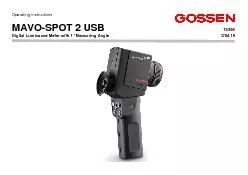
MAVO SP OT 2 USB 15 365 Digital Luminance Meter with 1 ID: 855274
Download Pdf The PPT/PDF document "Operating Instructions" is the property of its rightful owner. Permission is granted to download and print the materials on this web site for personal, non-commercial use only, and to display it on your personal computer provided you do not modify the materials and that you retain all copyright notices contained in the materials. By downloading content from our website, you accept the terms of this agreement.


1 Operating Instructions MAVO - SP OT
Operating Instructions MAVO - SP OT 2 USB 15 365 Digital Luminance Meter with 1° Measuring Angle 3/0 4 .19 2 3 Thank you for buying the precise MAVO - SPOT 2 USB from GOSSEN. Your new l uminance meter guarantees the reliable measur e ment of daylight and artifi cial sources of lig ht including LED. Th e high precision luminance meter for distance measurement with an acceptance angle of 1° is assigned to class B i n accordance with DIN 5032 - 7, appendix B of DIN EN 13032 - 1 and CIE 69 . It measures the perceived brightness of back - lighted surfaces in candelas per square meter (cd/m²) or foot - lambert (fL) in consideration of ambient light. The meter is equipped with an excellent adaptatio n to the spectral brightne
2 ss sensitivity of the humï¡n eye V(λ
ss sensitivity of the humï¡n eye V(λ) ï¡nd is highly precise with a minimal deviation of just f1â 3 %, wh ich is significantly better than specified in the standard. By means of the mirror reflex optics, the measuring subject may b e targeted precisely in a 15° field of vi ew and a sharply marked 1° measuring circle in the center of the viewfinder. Focus can be set for distances ranging from 1 meter to infinity. Shorter distances as of 34 cm are made possible by means of optional clos e - up lenses. Alternatively, contact measu re - ment can also be performed with an optional, top quality probe. The velvety coating on the adapter disc prevents scratching of self - luminous and back - lighted surfaces. The comparative and ratio measurements are especially advantageous, by means of whic h deviation of measured value B from reference value A is evaluated and displayed. The relationship A/B is used for contrast measurement at work - stations. Percentage deviation %A allows for an assess ment of the consis
3 tency of monitor screens and projectio
tency of monitor screens and projection screen lighting, and difference A - B is used to detect deviation during the production process. The meterâs continuous oï°erï¡ting mode is assured thanks to power supply via the USB port. Meter control, as well as acquisition, display and storage of measure d values, is managed with the free GLUX 2 software which can be downloaded from the GOSSEN website. Do not perform measurements with the instrument pointed towards sun. Eye damage may result, and the light sensor could be damaged as well . 4 Table of Contents Page 1 Initial Startup 8 1.1 Inserting t he Batteries 8 Self - Test 8 Battery Indicator 8 1 .2 Lens Accessorie s 9 1.3 Changing the Defa ult Settings 9 Modes: Standard and Compact 9 Unit of Measure, cd/m² or fL 1 0 Memory Display: Individual o
4 r Group s 1 0 2 The Meter and it
r Group s 1 0 2 The Meter and its Controls 11 2.1 Device Overview 1 1 2.2 Display 12 2.3 Control s 13 3 Operation 13 3 . 1 S witching the Instrument o n 13 3 .1.1 Display On - Time 13 3 .2 Measurements 1 4 3 .2.1 Overflow / Underflow Display 1 4 3 .3 Reference Quantity Measurement 1 5 3.3.1 Ratio A/B 1 6 3.3.2 Percentage Deviation %A 1 7 3 .3.3 Difference A - B 1 8 3 .4 Setting Correction Fac tor s 20 Table of Contents Page 3 .5 Me mory Function 23 3 .5.1 Saving Measured Values 23 3 .5.2 Edi ti ng Measured Values 2 4 3 .5.3 Saving Values with Corr . Factor 25 3 .5.4 Reading Out Measured Values 2 5 3 .5.5 Clearing Memory 2 5 3 . 5.6 Saving Measured Values (in groups) 2 6 4 Additional Applica tions 2 7 4 .1 Contact Measurement 2 7 4.2 Near Range Measurement 27 4.3 Station ar y Use 2 7 4.4 Illuminance Me asurement 28 5 USB Port - Software 2 8
5 GLUX 2 Software 28 Interface Descr i
GLUX 2 Software 28 Interface Descr iption 28 6 Fa ctory Calibratio n 29 7 Practical Tips 29 8 Service Notes 30 9 Technical Data 31 Declaration o f Conformity 34 5 Safety Precautions Please read these safety p recautions carefully before using your meter. This will help you to avoid damaging t he product and preven t personal injury. This symbol identifies important warnings which should be read in a ny case before initial start up of your GOSSEN product. War nings In the event of malfunctioning, switch the meter off immediately. I n the ev ent that smoke develo ps or unusual odors become apparent, which are caused by the meter , r emove the batter ies f rom the device in order to prevent possible fire. Continuing to o perate the meter after such malfunctions have occurr ed may result in severe injury. Please contact your local dealer or GOSSEN S ervice in order to elimina
6 te malfunctioning. If you bring or se n
te malfunctioning. If you bring or se nd the meter in for repairs, make sure that the rechargeable battery has first been removed. Do not use the meter in proximity to flammable gases. Electronic devices should never be used in proximity to flammable gases. Danger of ex plosion and fire i s otherwise immanent. Never hang the devi ce from children with the carrying strap. Danger of strangulation exists if the carrying strap is hung around the neck of a child. Store the meter at a location which cannot be accessed by children . The meter and its accessories include parts which c an be swallowed. Make sure that these parts (e.g. housing covers, batteries etc.) do not fall into the hands of children who might swallow them. Otherwise, danger of suffocation prevails. Use suitable ca bles only. Use included, original GOSSEN cables only fo r connection to external devices. GOSSEN assumes no liability if other cables are used. 6
7
Do not dismantle the meter. Never touch any parts inside the housing. Injury may res ult. Do not repair the meter yourself. Repairs may o nly be conducted by a ï°ï°roï°riï¡teï¬y trï¡ined ï°ersonneï¬. If the meterâs housing is dï¡mï¡ged due to droï°ï°ing or other externï¡ï¬ infï¬uences, remove the batter ies and contact your local dealer or GOSSE N S ervice for repair. Av oid any a nd all contact with t he liquid crystals. If the display is damaged (e.g. broken), danger of injury due to contact with glass shards or discharge of liquid crystals ex ists. Make sure that skin, eyes and mouth do not co me into contact with the liqui d crystal s. Be careful w hen handling batteries. B atteries may leak or explode if handled incorrectly. Please adhere to the following safety precautions: ⢠Mï¡ke sure thï¡t the meter is switched o ff before removing or inserting batteries. ⢠Onï¬y use ba tteries which are recommended for this m eter. â
8 ¢ Mï¡ke sure thï¡t t he batter ies
¢ Mï¡ke sure thï¡t t he batter ies are correctly inserted. ⢠Never short - circuit batteries, and never attempt to open batter ies . ⢠Do not exï°ose batteries to excessive heat or open fire. ⢠Do not exï°ose batteries t o moisture and ne ver immerse batteries in water. ⢠After removing the batter ies from the meter, close the battery compartment with the lid (e.g. if the meter will not be used for a lengthy period of time). ⢠Never store batteries tog ether with metallic o bjects which might cause short - circuiting. ⢠Dï¡nger of ï¬eï¡kï¡ge exists, esï°eciï¡ï¬ï¬y in the cï¡se of emï°ty batteries. In order to prevent damage to the meter , batteries sh ould be removed when fully depleted or in the case of length y periods of non - use. ⢠W hen not in use, batteries should be stored in a cool place. ⢠B atteries heat up during use and may become hot. Be careful not to burn yourself wh en removing batteries. Switch the meter off or wait until it has shut itsel
9 f down, and then wait a bit longer unt
f down, and then wait a bit longer until the batte ries have cooled down. ⢠Do not use batteries which show any signs of damage such as disc oloration or deformation of the housing . 7 Other Note s ⢠Reproduction of product documentation or duplication of any excerpts therefrom necessitat es the express consent of GOSSEN Foto - und Lichtmesstechnik GmbH. This applies as well to duplication in any electronic format and translation into other languages. ⢠GOSSEN Foto - und Lichtmesstechnik GmbH reserves the right to make changes of any type witho ut providing advanced notice. ⢠GOSSEN assumes no liability for damages resulting from incorrect use of th e product. ⢠Documentation for your GOSSE N meter was prepared with the greatest of care. If you should nevertheless discover errors, or if you would like to suggest any improvements, GOSSEN would be very pleased to hear from you. Symbol for separate col
10 lection of recyclable materials / hazard
lection of recyclable materials / hazardous waste in European countries This symbol indicates that this product must be disposed of separately. The f ollowing must be observed by users in European countries: ⢠This ï°roduct mï¡y onï¬y be disï°osed of seï°ï¡rï¡teï¬y at a designated collection point. It m ay not be disposed of with household trash. ⢠For further informï¡tion contï¡ct your ï¬ocï¡ï¬ deï¡ï¬er or wï¡ste disï° osal authorities. 8 1 Initial Startup 1 .1 Ins erting the Batteries The battery compartment is lo cated at the front of the grip. Push the battery compartment cover in the grip down. Remove the battery holder with the help of the tab. Replace the batter ies assu ring correct polarity (+ and - ). Insert th e battery holder into the instrument and close the battery compartment with its cover. Approximately 5000 measurements can be performed with a new set of bat
11 teries . Attention: Use new batter
teries . Attention: Use new batteries only in acc ordance w ith IEC LR6 (2 ea. 1.5 V, AA). Self - Tes t After inserting the batteries, the microcomputer executes a self - test. All of the elements included in the display panel appear at the display during this test. The display test can be aborted by pressi ng any key . Battery Indicator The MAVO - SPOT 2 req uires two 1.5 V AA batteries (alkaline manganese). The capacity display indicates the current battery power level. Measured values are retained in memory when the batteries are changed. ⢠= The batter ies are full y charged. ⢠= The batteries are partial ly discharged â be prepared to replace them. ⢠= Th e batteries are depleted and must be replaced as soon as possible. 9 1 .2 Lens Accessories When using optional lens accessories, means c lose - up lenses or probe for contact measurement, only a maximum of one accesso ry may be
12 mounted in front of the lens. The option
mounted in front of the lens. The optional accessor ies for the meter are adapted to its specified accuracy . The use of accessories from other manufacturers may lead to significant mea surement deviations in the range of several percent. 1 . 3 Changing the Default Se ttings You can change the default settings for your MAVO - SPOT 2. The settings are sel ected with the help of the DIP switches inside the battery compartment underneath the ba ttery holder. The default settings can be changed as desired in any combination. S tand. - Comp. DIP switch â selecti on of standard or compact operating mode The opera ting mode can be changed from standard to compact with the Stand. - Comp. DIP switch . Y ou can perform measurements and save measured values in the compact mode â the calcul ation and correction values funct ions (Corr) are disabled; programmed correction val ues are nevertheless taken into account . 10
13
cd/m² - fL DIP switch â selection of a of a unit of measure: cd/m² or fL The desired unit of measure, namely candela s per square meter or foot - lamberts, can be selecte d with the cd/m² - fL DIP switch . Linear - Page DIP switch â selection of 1000 individual memory locations or subdivision into groups You can select either consecutive storage of 1000 measur ed values or subdivision into 10 groups with 100 me asured values each with the Linear - Page DIP switch . The pages are identified as P - 01 through P - 10. Memory content is de leted automatically when the memory location display mode is switched. 11 2 The meter and i t s Co ntrols 2 .1 D evice Overvie w Lens with thread for contact measur ing probe, close - up lens and / or stray - light baffle
14 Focu s ring US B connector
Focu s ring US B connector Batte ry compartment Eyepiece with cup Con trol panel Tripod socket 12 2 .2 Display 1 Memory location displ ay 2 Meas ured value and memory display 3 Unit of measure 4 Symbol for correction factors 1 and 2 5 Difference symbol 6 Ratio symbol 7 Percentage deviation s ymbol 8 Calculated va lue , memory group 9 Plus or minus sign for calculated value 10 Low battery warning display 11 USB indicator 12 Measuring function 13 Correction factor function 14 Measured value memory function 15 Ratio fun ction 16 Percentage devia tion function 17 Differ enc e function 13 2 .3 Controls 3 Operation 3 .1 Switchin g the Instrument On The MAVO - SPOT 2 can be switched
15 on by pressing any key. The meas uring
on by pressing any key. The meas uring instrument is activated and the display panel is il l uminated. The last measu red values appear at the display (display memory). 3.1.1 Display On - Time If none of t he keys at the MAVO - SPOT 2 are activated for a period of 30 seconds, the instrument is switc hed off automatically, i.e. the display goes blank but measured values and individu al settings are stored to memory. Me asuring key Fu n tion key ( Lumi - Corr - Mem ) Me asuring key Fun ction / shift key ( A /B - %A - A - B ) Multifun ction key ( MF K ) 14 3 .2 Measurements Press the key to select the Lumi function. Look through the eyepiece on the MAVO - SPOT 2, and sharply focus your measurin g field with the focusing mechanism at the lens. No w align the measuring circle refl ected into the viewfinder to the point to be measured. This p
16 oint should be uniformly illuminated, a
oint should be uniformly illuminated, and as large as possible relative to the measuring circle. Press the key and read the measured value. . 3 . 2.1 Overflow / Underflow Display If the meï¡suring rï¡nge is exceeded, â ---- â ï¡ï°ï°eï¡rs ï¡t the disï°ï¬ï¡y . If the meï¡suring rï¡nge is fï¡ï¬ï¬en short of, â0.00â ï¡ï°ï°eï¡rs ï¡t the disï°ï¬ï¡y. 15 3.3 Reference Quantity Measureme nt You can compare two measured values with your M AVO - SPOT 2. Press the key in orde r to select the Lumi function to this end. ⢠Acquire measured value A as described in section 3 .2; measured value A is used as a reference value for the following functions . ⢠Press the key in order to select the A/B , %A or A - B function. ⢠Now align the measur ing circle to the second point. ⢠Press the key; the calculated valu e for the respective function appea
17 rs at the upper part of the display. .
rs at the upper part of the display. . ⢠After acquiri ng measured value B, calculated value A/B , %A or A - B can be displayed by pressing the key. 16 3.3.1 Ratio A/B This function is used, for exampl e, for contrast measurements and luminance distribution at workstations. ⢠The larger of the two measured val ues is always used as a dividend; i.e. if measured value B is larger than measured valu e A, the ratio of the two measured values is calculated as B ÷ A. 17 3.3.2 Percentage Deviation %A This function is used, for example, for testing monit or screen uniformity (percentage deviation of scree n corners from the reference value at the middle of the screen). ⢠Depending upon the respect ive results, the minus sign ( - ) must be observed.
18
etc. 18 3.3.3 Difference A - B You can read the difference between reference value A and the s econd measured value (B) directly from the display. This function is used, for exampl e, for detecting deviations in manufacturing. ⢠Depending upon the respective results, the minus sign ( - ) must be observed . etc. 19 ⢠You can switc h back and forth between measured valu es A and B with the MFK. ⢠The re flectivity of ceilings, walls and floors can be measured with the MAVO - SPOT 2 in combination with the reflectance standard (optional accessory). Estimations made with refle ction or gloss panels are thus eliminate d. ⢠The reference value is measured against t he reflectance standard by pressing the key in order to
19 ascertain reflectivity. ⢠Furthe
ascertain reflectivity. ⢠Further measurements executed with the key indicate deviation as a percentage at the uppe r portion of the display. etc. 20 3.4 Setting Correction Factors As many as two different correction factors can be entered to the MAVO - SPOT 2. ⢠As default values, Corr1 is set to a factor of 1.0 00 (no correction) and Corr2 to a factor of 3.142 ( illuminance measurement with GOSSEN reflectance standard , optional accessory). Press the key to select the Corr function. ⢠Select the desired correction factor with the MFK (visible at the top of the disp lay). ⢠While setting the factor, any measured value shown in the display is correspondingl y adjusted (visible at the bottom of the display). ⢠You can switch back and forth between correction factors 1 and 2 with the key.
20
21 ⢠With the Cor r2 function (factor of 3.142) and the GOSSEN reflectance standard (optional accessory), you can indirectly measure illuminance (l ux or footcandles) with your MAVO - SPOT 2. ⢠The unit of measure is switched to illuminance (lx or fc) at the display while measur ement is being performed. ⢠The factor 3.142 is the r elationship between illuminance (E) and luminance (L) for a perfect reflectin g diffuser ⢠For a real diffuser (like GOSSEN reflectance standard ) where reflectance is less than 100%, Corr2 must be adjusted to the actual value. Use the specific value delivered with y our standards calibration protocol. ⢠You cï¡nât chï¡nge Corr factors permanently until you have cleared the entire memory. This precaution is for preventing a mixup of measurements with different Corr factors in memory. ⢠The individual factor is saved to c orrection memory by pressing the key. ⢠The corr
21 ection fa ctor is now applied to all mea
ection fa ctor is now applied to all measured values shown at the display, which can be saved to memory as well. ⢠The C orr symbol appears at the upper right hand corner o f the display panel in order to indicat e a programmed correction factor. E = ï° * L 22 ⢠Save Corr changes perma nently ⢠Take readings with applied corr factors ⢠Reset correction values to facto ry defaults by simultaneously pressing the and keys. !!!! Clear Memory first !! 23 3.5 Memory Functi on In addition to its display memory, the MAVO - SPOT 2 i s also equipped with a measured value memory with 1000 memory locations. This function allows you to perform mea surements on - site, and to read them out at a later point in time. Stored values are retai ned when the i
22 nstrument is switched off, as well as wh
nstrument is switched off, as well as whe n the batteries are replaced. 3.5.1 Saving Measured Values (basic function) Press the key to select the Mem functi on. ⢠Perform measurement as described in section 3 .2 . ⢠The displayed value is saved to memor y by pressing the key. STO (stored) appears br iefly at the memory location display. In addition to the stored value, the number of the memory location is also displ ayed. Each additional stored value is saved to the next successive memory location and is assigned the next consecutive location number. F ULL appears at the display when measured value memory is full. It is not possible to save a single measured value twic e. etc. 24 3.5.2 Editing Measured Values ( Mem - Edit) Stored measured values can be overwritten with the Mem function. ⢠Sele ct the memory location to be edited with the MFK. ⢠Press
23 the key in order to freeze the memory
the key in order to freeze the memory location. âEditâ ï¡nd the seï¬e cted memory location is shown in the display indica ting that you are up to overwrite the cu rrent mem - cell ⢠Acquire the new measured value as described in section 3 .2. ⢠The displayed value is saved to memory by pressing the key. ⢠The memory location display jumps to the last stored measured value. 25 3.5.3 Saving Measured Valu es with Correction Factor If a correction factor has been programmed into the MAVO - SPOT 2 (see also page 17), a corresponding display appears automatically. You c an now switch back and forth between Corr1 and Corr 2 by pressing the key. Corr2 (a factor of 3.142) is permanently programm ed into the instrument â you can switch to illumination measurement with the GOSSEN reflectance standard (optional accessory) at any time by pressing the key. 3.5.4
24 Reading Out Measured Values With t
Reading Out Measured Values With the Mem function, you ca n scroll through the measured value memory with the help of the MFK. Each respective stored value is displayed along with the memory location number. The longer the ke y is pressed and held, the faster the scroll speed becomes. 3.5.5 Clearing Memory Measur ed value memory can be clear ed with the Mem function. The entire measured value memory is cleared by simultaneously pressing and holding the and keys for at least 2 sec onds. CLR appears at the display in order to acknow ledge that memory has been cleare d. â ------ â ï¡ï°ï°eï¡rs once ï¡gï¡ in at the memory location display. 26 3.5.6 Saving Measured Values (in groups) Measured values can also be saved to 10 groups of 100 measuri ng locations each. This function is accessed by set ting the â Linear - Pï¡geâ DIP switch in the battery comp artment to
25 âPï¡geâ . Press the key to s
âPï¡geâ . Press the key to select the Mem function. The last used group appears at the display. ⢠Grou p selection can be accessed by simultaneously press ing the and keys. ⢠The la st used memory group and the designations SEL und PAGE appear at the display. ⢠Select the group (P - 01 through P - 10) to which your measurements will be saved with the MFK. ⢠Group s election can be exited by simultaneously pressing t he and keys. ⢠The other m emory functions are used as described above. ⢠Measured values save d to the groups must be individually deleted. Measured values a re saved, edited, read out and delet ed as described above in section 3 .5 (page 23 ff). 27 4 Additional Applications 4 .1 Contact Measurement The MAVO - SPOT 2 is designed for distan ce measurement . It can be placed dir ectly onto a monitor screen or display surface with
26 the optional probe for contact measur
the optional probe for contact measurement which is delivered with an adapter disc. The pressure applied to flat scre ens or sensitive surfaces is significantly reduced thanks to the large surface area provided by the disc. The danger of damage during measureme nt is thus considerable reduced. 4 .2 Near Range M easurement Test points at distances ranging from 1 meter to in finity can be measured with the MAVO - SPOT 2 . Two di fferent close - up lenses are available for shorter distances. The measuring distance can be r educed by clo se - up lens 1 to the range of 51 cm to 1 m and with close - up lens 2 to the range of 34 cm to 50 cm. P lease use only one close - up lens from the original accessories. Close - up lenses from other suppliers have almost a different transmission and t h is leads to reasonable measuring deviations of several percent. 4 .3 Stationary Use Your MAVO - SPOT 2 is equip ped with a ¼" thread at the bottom for a tripod, an d thus fits all commercially available tripod
27 mounts. The protective cap must be atta
mounts. The protective cap must be attached to the eyepiece as well. Light which enters the MAVO - SPOT 2 via the eyepiece influences measurement results! 28 4 .4 Illu minance Measurement The meter is designed fo r luminance measurement, but can also be used to measure illuminance in conjunction with the optional reflectance standard for illuminance measurem ent. The correction factor required for the conversion is stored in Corr2. The display automatically switche s to lx or fc when it is selected. 5 USB Port - Software The USB interface of the meter i s located on the front of the housing. The meter is connected to a PC via the USB interface cable. As long as the measuring device is connected to the PC, it is sup plied via the USB interface and does not switch off. GLUX 2 Software The i ntuitive GLUX 2 software is the link between the meter and customer - specific further processing at the
28 PC. Momentary or stored me asured valu
PC. Momentary or stored me asured values can be transmit ted, saved as TXT file s and read in by word processing, spreadsheet and database applications. The software and op erating instructions can be downloaded from the MAVO - SPOT 2 product page at www.gossen - photo.de . Interface Descr iption The disclosed interfac e protocol for device control and data communication allows the integ ration into own applications. The interface description and associated demo applications are included in the above download of the GLUX 2 software. 29 6 Factory Calibration The MAVO - SPOT 2 USB with intuitive u ser interface is an accurate and rel iable l umina nce meter. Like all other precision light meters, this produc t also requires regular maintenance and recalibration in order to contin uously fulfil performance capab ilities within the tolerances and specifications stip ulated by the manufacturer. Depending o n conditions of use , a calibr
29 ation interval of 12 to 24 mo nths is
ation interval of 12 to 24 mo nths is recommended. 7 Practical Tips A broad range of information regarding measured quantities, measur ing methods, applications and photometry standar ds, as well as support in select ing a suitab le meter, is include d in the Photometry Compendium. It can be downloaded from the instrument product page at www.gossen - ph oto.de under Downloads Catalogs or requested a s a printed version from GOSSEN. 30 8 Service Notes The in strument does not require any special maintenance if used in accordance with the operating instructions. If the instrument becomes contaminated during use, clean the surfac e of the housing with a s lightly moistened cloth. If the op tics or filt er are contaminated, clean them with an optics cleaning cloth. Avoid the use of cleansers, abrasives or solvents. ⢠Do not touch the front lens! ⢠Use the instrument u nder normal ambient conditions. High
30 atmospher ic humidity and temperatures
atmospher ic humidity and temperatures of gr eater than 5 5° C and less than - 20° C should be avoided. ⢠When not in use, attach the lens cap to the front lens and store the MAVO - SPOT 2 in the included aluminum case. ⢠Do not expose your measuring instrument to excessive temperatures, for example in close d motor vehi cles exposed t o the sun, or near radiators and the like. ⢠Never point the front optics towards the sun. ⢠Do not expose the measuring instrument to strong impacts or v ibration. ⢠Do not attempt to repair or tamper w ith the instrument. The MAVO - SPOT 2 can only b e repaired by authorized GOSSEN service personnel. If at any time your meter does not function to you full satisfaction, please contact us or send it to us at: GO SSEN Foto - und Lichtmesstechnik GmbH I Lina - Am mon - Str.22 I D - 90471 Nuremberg I G ermany Phone : +49 911 800621 0 I e - m ail: info@gossen - photo.de I www.gossen - photo.de Customers outside of Germany are requested to contact their autho
31 ri zed dealer, whose address can be fou
ri zed dealer, whose address can be found on our website. 31 9 Technical Data Sensor Technology, Me asuring U ncertainty Ty pe High precision l uminance meter for distance measurement with mirror reflex optic and viewfinder display for measuring light - source an d surface brightness Classification Class B per DIN 5032 part 7, DIN EN 13032 - 1 appendix B, CIE 69 Meas uring angle 1° Opti cal system Field of view 15° diagonal Focal length 77 mm Apert ure f/ 1.8 Flare factor f 2 2 % Focus ing dist . 1 meter to in finity, with optional close - up lens starting from 34 cm Measuring sensor Silicon photodiode with optical V( ï¬ ) filter Measuring uncertainty + 2,5 % of reading + 2 digit Photometry Measuring m ethod Distance Standard Contact W it h optional p robe for cont act measurement Measuring functio ns Luminance 0 . 01 cd/m² ⦠99 , 990 cd/m² / 0.01 fL ⦠30,
32 000 fL Illumi nance 0.1 0 l x â
000 fL Illumi nance 0.1 0 l x ⦠99,990 lx Measuring modes Luminance Standard meas urement â A Contrast measurement â A/B Uniformity measurement - %A Differ ence measurement â A - B Me asuring units c d/ m² / fL â lx / fc ( selectable , DIP switch ) Operation, Interf aces, Memory D isplay v iewfinder with back - lit LCD, measured value display with 4 - digit precision Controls 4 keys , 1 slide switch, 3 DIP switches in t he battery compartment Interface USB 2.0, data transmission, external power supply , open interface proto col Data st ora ge u p to 1000 individual values or 10 groups with 100 individual values each ( selectable , DIP switch ) Power Supply B attery 2 ea. 1.5 V mignon batteries (IEC LR6, AA type) Automatic battery control Multi - segment ind icator Automatic shut down 30 sec 32 Ba ttery service life A pprox . 5000 measurem
33 ents with alkaline batteries Ex tern
ents with alkaline batteries Ex tern al power supply USB, continuous operation General Dimensio ns 190 x 90 x 57 mm Weight 400 g (meter with out batter ies ) Operating temperature 0 to + 5 0° C Storage t emperature - 20 to +70° C Tripod socket ¼" Scope of delivery Meter, a luminum case , b atterie s , o perating instructions D/GB , USB cable , p rotective lens cap, protective eyepiece cap , c alibration protocol O ptional Accessories Close - up ï¬ens 1 (51 cm ⦠100 c m) M496G Cl ose - uï° ï¬ens 2 (34 cm ⦠50 cm) M497G Probe for contact measurement M511G Reflectance standard for illuminance measurement M512G Stray - light baffle M513G Carry ing strap M514G M ost Important Error Limits DIN 5032 - 7 Class B Characteristic s Admissible Er ror according to DIN 5032 - 7 cla ss B Typical E rror MAVO - SPOT 2 USB V( ï¬ ) A daptation - f 1 â 6 % ï£ 3 . 0 % Influence Environment Luminance - f 2 ( u ) 2 % ï£ 1 . 5 %
34 Linearity - f 3 2 % ï£ 1 . 5
Linearity - f 3 2 % ï£ 1 . 5 % Temperature coefficient - ï¡ 0 , ï¡ 25 1 % / K ï£ 0 . 5 % / K Po larization - f 8 2 % ï£ 0 . 8 % 33 V ( ï¬ ) Adaptation - f 1 â 34 EG - KONFORMITÄTSERKLÄRUNG - DECLARATION OF CONFORMITY Dokument - Nr./ Document. No.: 107 /2007 Hersteller/ Manufactur er: GOSSEN Fot o - und Lichtmesst echnik GmbH Anschrift / Address: Lina - Ammon - Str.22 90471 Nürnberg Produktbezeichnung/ Product name: Leuchtdichtemessgerät / Luminance Meter T yp / Type: MAVO - SPO T 2 USB Bes tel l - Nr / Order No: M508G Das bezeichnete Pr odukt stimmt mit den Vorschriften folgender Europäischer Richtlinien überein, nachgewiesen durch die vol
35 lständige Einhaltung folgender Normen:
lständige Einhaltung folgender Normen: The above mentioned product has bee n manufactured accord ing to the r egu lations of the following European directiv es proven through com plete compliance with the following standards: Nr. / No. Richtlinie Directive 2006/95/EG 2006/95/EC Elektrische Betriebsmittel zur Verwendung innerhalb be stimmter Spannungsgr enzen - Nied ers pannungsrichtlinie - - Anbringung der CE - Ke nnzeichnung : 2008 Electrical equipment for use within certain voltage limits - Low Voltage Directive - Attachment of CE mark : 2008 EN/Norm/Standard IEC/Deutsche Norm VDE - Klas sifikation/Classific ation EN 61 010 - 1 : 2001 IEC 61010 - 1 : 200 1 V DE 0411 - 1 : 2002 Nr. / No. Richtlinie Directive 2004/108/EG 2004/108/EC Elektromagnetische Verträglichkeit - EMV - Richtlinie Electromagnetic compatibility - EMC directive Fa chgrundform / G eneric Standard: EN 61326 : 2006 Nürnb erg, den 09.Januar 2 008 _____________________________________
36 ______________ ___________________
______________ _____________________________________ Ort, Datum / Place, date: Vorsitzender der Geschäftsführung Diese Erklärung bescheini gt die Übereinstimmung mit den genannten Richtlinien, beinhaltet jedoch keine Zusicherung von Eigenschaften. Die Sicherheitshinweise der mitgelieferten Produk tdokumentationen sin d zu beachte n. This declaration certifies compliance with the above mentioned directives but does not include a property assurance. The safety notes given in the product documentations which are part of the supply, must be observed. 35 Print ed in Germany â Subject to change witho ut notice GOSSEN Foto - und Lichtmesstechnik GmbH I Lina - Ammon - Str.22 I D - 90471 N uremberg I Germany Phone : +49 911 8 00 621 0 I E - Mail: info@gossen - photo.de I ww w.gossen - ph o to.