
Matthew D Grant MD Ryan D Mann MD Scott D Kristenson MD Richard M Buck MD Juan D Mendoza MD Jason M Reese DO David W Grant DO Eric A Roberge MD From the Departments of Radiology MDG RDM SDK RMB JDM DWG EAR and Cardiology JMR Madigan Ar ID: 908838
Download Presentation The PPT/PDF document "Transthoracic Echocardiography: A Beginn..." is the property of its rightful owner. Permission is granted to download and print the materials on this web site for personal, non-commercial use only, and to display it on your personal computer provided you do not modify the materials and that you retain all copyright notices contained in the materials. By downloading content from our website, you accept the terms of this agreement.


Slide1
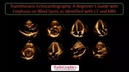
Transthoracic Echocardiography: A Beginner’s Guide with Emphasis on Blind Spots as Identified with CT and MRI
Slide2Matthew D. Grant, MD, Ryan D. Mann, MD,
Scott D. Kristenson, MD, Richard M. Buck, MD, Juan D. Mendoza, MD, Jason M. Reese, DO, David W. Grant, DO, Eric A. Roberge, MD
From the Departments of Radiology (M.D.G., R.D.M., S.D.K., R.M.B., J.D.M., D.W.G., E.A.R.) and Cardiology (J.M.R.), Madigan Army Medical Center, 9040 Jackson Ave, Tacoma, WA 98431; and the Uniformed Services University of the Health Sciences, Bethesda, Md (M.D.G., J.M.R., D.W.G., E.A.R.). Recipient of a Certificate of Merit award for an education exhibit at the 2019 RSNA Annual Meeting.
Slide3Disclosures
The authors have disclosed no relevant relationships.The views expressed are those of the authors and do not reflect the official policy of the Department of the Army, the Department of Defense, or the U.S. Government.
Abbreviations: CTA = CT angiography, ECG = electrocardiography, LA = left atrium, LAA = left atrial appendage, LV = left ventricle, RA = right atrium, RV = right ventricle, TTE = transthoracic echocardiography
Abbreviations: ASD = atrial septal defect, CECT = contrast-enhanced CT, CTA = CT angiography, ECG = electrocardiography, IAS = interatrial septum, IVC = inferior vena cava, LA = left atrium, LAA = left atrial appendage, LV = left ventricle, RA = right atrium, RV = right ventricle, 2D = two-dimensional, 3D = three-dimensional, TTE = transthoracic echocardiography
Slide4Teaching Points
While cardiac findings are generally best evaluated with ECG-gated cardiac CTA or cardiac MRI, in some instances a cardiac finding that was not present or not noticed at prior TTE may be apparent at nongated
chest CT or MRI.
For image acquisition, the window is defined as the position of the transducer on the patient. The four standard windows used in TTE are the parasternal, apical, subcostal, and suprasternal windows. The image plane refers to the orientation of the transducer in relationship to the axis of the LV. The four standard planes are the long-axis, short-axis, apical four-chamber, and apical two-chamber planes. Slightly off-axis planes may be acquired by gently tilting the transducer. The combination of the window, the plane, and the structures evaluated defines the echocardiographic view.
Evaluation of the pericardium at TTE is inherently limited owing to its generally thin nature, relatively low echogenicity, and poor tissue contrast against the adjacent myocardium and lungs. CT and MRI generally show the pericardium better owing to the much higher tissue contrast resolution of the pericardium in relation to the surrounding fat and air in the lungs at CT.
When the LV apex becomes aneurysmal, the finding can be missed at TTE, as the true apex will often extend beyond its usual visualized location. Although the apex is seen best on the apical three-chamber view and to some degree on the apical two-chamber view, the interpreting physician might be overconfident in their visualization of the true LV apex and may miss an aneurysm extending beyond the field of view.
Limitations in complete visualization of prosthetic valve components due to posterior acoustic shadowing can be overcome by using both cardiac CTA and cardiac MRI as adjuncts in evaluation of patients with prosthetic valve replacements.
Slide5Common Indications for Echocardiography
Many indications (acute and chronic):Valvular heart disease (
eg, murmur at physical exam): stenosis, regurgitation, prosthetic valve function, endocarditis
Coronary artery disease: acute myocardial infarction, angina, pre/post-revascularization (
ie, assessing the effect of therapy), end-stage ischemic disease
Cardiomyopathy (
eg, enlarged heart on chest x-ray or signs or symptoms of heart failure): dilated, restrictive, hypertrophic (
eg
, obtaining left ventricular ejection fraction for prognostic reasons)
Hypertension
Heart failurePericardial disease
Aortic disease: dilatation, dissection
Cardiac mass: thrombus, tumors
Pulmonary hypertension
Congenital heart disease
Arrhythmia (
eg
, supraventricular tachycardia, ventricular tachycardia)
Syncope, transient ischemic attack/stroke, peripheral embolism
Appropriateness criteria have been developed by the American College of Cardiology in collaboration with other organizations that provide helpful guidance, although not all possible clinical situations are included.
Slide6Transducer Selection
2D TTE generally uses a phased-array transducer with the ultrasound signal originating from a single location sector, or fan-shaped, image that allows a wide field of view in relation to the small transducer footprint
fast frame rate to compensate for cardiac motion
small transducer size enables evaluation in narrow acoustic windows
most provide simultaneous imaging and Doppler US analysisDifferent transducer types and transmission frequencies are needed for specific clinical applications
more than one transducer may be needed for a full examination (
eg
, 2D vs 3D transducers)Adjust multiple instrument settings and parameters as needed
for example, a higher transducer frequency provides improved resolution but less penetration
Slide7Strengths
PortableLow cost
Widely availableNo ionizing radiation
Functional assessment
Complementary to cardiac CT and MRI
Slide8Limitations and Pitfalls
Limitations:poor acoustic windows (large body habitus, incompletely visualized apical lesions, obstructive airway disease, recent cardiothoracic surgery)
limited windows (difficult to see extracardiac tumors; complicated congenital heart disease anatomy)
narrow fields of view
operator dependent
may underestimate valve stenosisdifficult to see atrial appendage (
eg, exclude thrombus)
Pitfalls:
blind spots
p
ericardium
a
orta
l
eft
v
entricular
a
pex
c
ardiac
v
alves
left atrial appendage
c
oronary
a
rteries
e
xtracardiac
structures
artifacts
masses and mimics
Slide9Windows
and Planes create the View
There are four standard windows, each with various planes to create the view:
Parasternal
Apical
Subcostal
Suprasternal
Window
= location of transducer on patient
Plane
= orientation in relationship to the axis of the
LV
View
= combination of the window, the plane, and the structures evaluated
Standard echocardiographic windows
at
TTE (left) and standard imaging planes (right).
The four standard windows are parasternal, apical, subcostal, and suprasternal.
The four standard planes are long
axis, short
axis, apical four
chamber, and apical two
chamber.
AO
= aorta,
PA
= pulmonary artery,
LV
= left ventricle,
RA
= right atrium
, RV
= right ventricle,
Sup
= suprasternal notch. (Reprinted, with permission, from reference 9.)
Slide10Windows
and Planes create the View
Parasternal window (and views)
Long axis, left ventricle (or parasagittal)
Long axis, right ventricle (inflow-outflow)
Short axis, aortic valve level
Short axis, mitral valve levelShort axis, papillary muscle level
Short axis, apical level
Window
= location of transducer
Plane
= orientation in relationship to the axis of the
LV
View
= combination of the window, the plane, and the structures evaluated
Standard echocardiographic windows on TTE (left) and standard imaging planes (right).
The four standard windows are parasternal, apical, subcostal, and suprasternal.
The four standard planes are long-axis, short-axis, apical four-chamber, and apical two-chamber.
AO
= aorta,
PA
= pulmonary artery,
LV
= left ventricle,
RA
= right atrium
, RV
= right ventricle,
Sup
= suprasternal notch. (Reprinted, with permission, from reference 9.)
Slide11Windows
and Planes create the View
Apical
Four chamber
Three chamber (long axis, left ventricle)
Two chamber
Five chamber
Window
= location of transducer
Plane
= orientation in relationship to the axis of the
LV
View
= combination of the window, the plane, and the structures evaluated
Standard echocardiographic windows on TTE (left) and standard imaging planes (right).
The four standard windows are parasternal, apical, subcostal, and suprasternal.
The four standard planes are long-axis, short-axis, apical four-chamber, and apical two-chamber.
AO
= aorta,
PA
= pulmonary artery,
LV
= left ventricle,
RA
= right atrium
, RV
= right ventricle,
Sup
= suprasternal notch. (Reprinted, with permission, from reference 9.)
Slide12Windows
and Planes create the View
Subcostal
Four chamber
Inferior vena cava (and other)
Window
= location of transducer
Plane
= orientation in relationship to the axis of the
LV
View
= combination of the imaging window, plane, and the structures evaluated
Standard echocardiographic windows on TTE (left) and standard imaging planes (right).
The four standard windows are parasternal, apical, subcostal, and suprasternal.
The four standard planes are long-axis, short-axis, apical four-chamber, and apical two-chamber.
AO
= aorta,
PA
= pulmonary artery,
LV
= left ventricle,
RA
= right atrium
, RV
= right ventricle,
Sup
= suprasternal notch
. (Reprinted, with permission, from reference 9.)
Slide13Windows
and Planes create the View
Suprasternal
Long axis, aortic arch
Window
= location of transducer
Plane
= orientation in relationship to the axis of the
LV
View
= combination of the window, the plane, and the structures evaluated
Standard echocardiographic windows on TTE (left) and standard imaging planes (right).
The four standard windows are parasternal, apical, subcostal, and suprasternal.
The four standard planes are long-axis, short-axis, apical four-chamber, and apical two-chamber.
AO
= aorta,
PA
= pulmonary artery,
LV
= left ventricle,
RA
= right atrium
, RV
= right ventricle,
Sup
= suprasternal notch
. (Reprinted, with permission, from reference 9.)
Slide14Parasternal Window: Long-Axis, Left Ventricle (or Parasagittal) View
Strengths
Structures visualized: aortic root
(annulus, valve, sinuses of Valsalva,
sinotubular junction, coronary ostia), proximal 3 to 4 cm of ascending aorta, mitral valve, LV septum and posterior wall, LV outflow tract, LA, coronary sinus, descending thoracic aorta, RV outflow tract
Limitations
True LV apex not visualized (“apex” actually oblique image through anterolateral wall)
TTE (left) and CECT (right):
*
= left ventricular outflow tract, arrowhead = aortic valve, arrow = mitral valve,
AR
= aortic root,
DAo
= descending aorta,
IVS
= interventricular septum,
LA
= left atrium,
LV
= left ventricle,
RV
= right ventricle.
Slide15Parasternal Window: Long-Axis, Right Ventricle (Inflow-Outflow) View
Strengths
Structures visualized: RA (possible crista terminalis), tricuspid valve, RV (and moderator band), coronary sinus, IVC (possible eustachian valve or Chiari network)
Limitations
IAS not well seen (inferior and parallel to imaging plane)
Right atrial
a
ppendage
rarely visualized
at
TTE
TTE (left) and CECT (right): arrow = tricuspid valve,
*
= coronary sinus,
RA
= right atrium,
RV
= right ventricle.
Slide16Parasternal Window: Short-Axis, Aortic Valve Level View
Strengths
Structures visualized: aortic valve (and cusps), coronary arteries (possible), LA, RA, IAS, RV, right ventricular outflow tract, proximal pulmonary arteries, pulmonic valve (orthogonal to aortic valve)
Shows the close relationship between the
aortic valve
and other intracardiac structures
Limitations
Pulmonic valve evaluation in adults is limited; usually only one or two leaflets are seen well, and a short-axis view often is not obtainable
TTE (left) and CECT (right): arrow = tricuspid valve, arrowhead = pulmonic valve,
LA
= left atrium,
LAA
= left atrial appendage,
LC
= left coronary cusp,
MPA
= main pulmonary artery,
NC
= noncoronary cusp,
RA
= right atrium,
RC
= right coronary cusp,
RV
= right ventricle.
Slide17Parasternal Window: Short-Axis, Mitral Valve (Basal) Level View
Strengths
Structures visualized: RV (anterior), LV, interventricular septum, mitral valve (“fish mouth” appearance; anterior and posterior leaflets), chordae
TTE (left) and CECT (right): arrow = anterior mitral valve leaflet, arrowhead = posterior mitral valve leaflet,
RV
= right ventricle.
Slide18Parasternal Window: Short-Axis, Papillary Muscle (Mid-Ventricular) Level View
Strengths
Structures visualized: anterolateral (AL) and posteromedial (PM) papillary muscles, RV, LV
Limitations
LV apex not visualized
LV may appear elliptical (rather than circular)
owing
to angle of the probe or changes during systole and diastole
May simulate myocardial disease
May lead to overestimation of LV wall thickness if oblique
TTE (left) and CECT (right): arrow = anterolateral papillary muscle, arrowheads = posteromedial papillary muscle,
LV
= left ventricle,
RV
= right ventricle.
Slide19Parasternal Window: Short-Axis, Apical Level View
Strengths
Structures visualized: LV apex
Limitations
May not see apical segment on standard parasternal views (move transducer lateral and angle medial or use 3D volumetric imaging)
TTE (left) and CECT (right):
LV
= left ventricle,
RV
= right ventricle. Although not required, the RV is visible in addition to the LV in this example.
Slide20Apical Window: Four-Chamber View
Strengths
Structures visualized: four cardiac chambers in one plane (atria and ventricles), mitral valve (MV), tricuspid valve (TV) (up to 1.0 cm more apically oriented than MV), descending thoracic aorta
Limitations
If transducer not positioned right at the apex, this could contribute to a foreshortened appearance of the LV and simulated disease (such as aortic regurgitation)
Increased
trabeculation
in the LV may simulate thrombus
Atria are far away, so detailed evaluation (
eg
, for thrombus) is poor and may require
transesophageal echocardiography
IAS is oriented parallel so may not reflect US beam, simulate
atrial septal defect
TTE (left) and CECT (right): straight arrow = mitral valve, curved arrow = tricuspid valve,
LA
= left atrium,
LV
= left ventricle,
RA
= right atrium,
RV
= right ventricle.
Slide21Apical Window: Five-Chamber View
Strengths
Structures visualized: left ventricular outflow tract (LVOT), aortic valve, interventricular septum, lateral wall
TTE (left) and CECT (right): arrowhead = aortic valve,
*
= left ventricular outflow tract,
LA
= left atrium,
LV
= left ventricle,
RA
= right atrium,
RV
= right ventricle.
Slide22Apical Window: Two-Chamber View
Strengths
Structures visualized: LV, mitral valve
, LA, and LAA (which may be better seen with a dilated LA or on transesophageal echocardiogram)
Direct visualization of the true inferior and anterior wall of the LV
May visualize thrombus in the LV apex or LAA
Limitations
Although LV apex visualized, aneurysms extending beyond the field of view may be missed
Interference from adjacent lung tissue
TTE (left) and CECT (right): arrowhead = mitral valve,
*
= left atrial appendage, curved arrow = pulmonary vein,
LA
= left atrium,
LV
= left ventricle.
Slide23Apical Window: Long-Axis, Left Ventricle (Apical Three-Chamber) View
Strengths
Structures visualized: aortic and mitral valve, LV outflow tract, LV apex
Best view of LV apex
Limitations
Overconfidence in visualizing the apex, leading to missed apical aneurysms that extend beyond the field of view
Worse resolution of aortic and mitral valves due to greater image depth (compared to parasternal long axis)
TTE (left) and CECT (right): straight
a
rrow
= aortic valve,
AR
= aortic root, curved arrow = mitral valve,
LA
= left atrium,
LV
= left ventricle.
Slide24Subcostal Window: Four-Chamber View
Strengths
Structures visualized: great visualization of the atrial and ventricular septa, may be able to evaluate IVC (estimate right atrial pressures), hepatic veins, liver, and abdominal aorta, RV free wall, anterolateral LV wall
Liver readily transmits sound waves
Great for ASD evaluation (IAS perpendicular to the sound beam)
May be the only good window
for
intensive care unit setting (especially if chest wall injury, hyperinflated lungs, or pneumothorax)
Excellent in infants and small children
TTE (left) and CECT (right):
LA
= left atrium,
LV
= left ventricle,
RA
= right atrium,
RV
= right ventricle.
Slide25Subcostal Window: Inferior Vena Cava (and Other Structures) View
Strengths
Structures visualized: IVC as it enters the RA (+/- hepatic veins and abdominal aorta)
Estimate right atrial pressure by changes in size of the IVC during respiration (collapsibility
index
)
TTE (left) and CECT (right):
IVC
= inferior vena cava,
LA
= left atrium,
RA
= right atrium.
Slide26Suprasternal Window: Long-Axis, Aortic Arch View
Strengths
Structures visualized: long-axis view of the aortic arch, brachiocephalic, left common carotid, and left subclavian artery origins
Able to evaluate for aortic dissection, coarctation, or supravalvular enlargement
Limitations
Oblong view of the arch instead of a true short-axis view, decreasing accuracy of ascending aorta and arch measurements
TTE (left) and CECT (right):
Ao
= aorta,
BC
= brachiocephalic artery,
LCC
= left common carotid artery,
LSC
= left subclavian artery,
RPA
= right pulmonary artery.
Slide27Blind Spot Examples
Slide28TTE Blind Spots
Pericardium:
pericarditis (acute or chronic/constrictive), effusions (transudative or exudative; with or without loculation or tamponade), masses (benign or malignant), congenital abnormalities (
eg
, congenital absence), pericardial thickening, calcification, cysts, diverticulum, hematomas, metastatic disease
Aorta : aneurysm, dissection, penetrating atherosclerotic ulcer, intramural hematoma
LV apex: intracardiac thrombus, apical aneurysm (and pseudoaneurysm), apical hypertrophic cardiomyopathy, infarctCardiac valves: endocarditis and associated complications include valvular stenosis, leaflet perforation, paravalvular leak, dehiscence of prosthetic valves,
pseudoaneursym, or perivalvular abscess formation, prosthetic valvular pathology (posterior acoustic shadowing limits evaluation of valve function and morphology),
hypoattenuated leaflet thickening (HALT)--subclinical leaflet thrombosis, aortic valve calcification
LAA: thrombus
Coronary arteries: anomalous origins, fistulas, aneurysms, benignExtracardiac: benign (eg, hiatal hernia, hepatic cysts, cholelithiasis), masses (benign or malignant), pleural effusions, ascites
Miscellaneous: small septal defects (atrial and ventricular), small pseudoaneurysms, nonischemic cardiomyopathies (limited characterization), incompletely visualized eustachian valve
Slide29Blind Spot #1: Pericardium
pericarditis (acute or chronic/constrictive)
effusions (transudative or exudative; with or without loculation or tamponade)
masses (benign or malignant)
congenital abnormalities (
eg
, congenital absence)
pericardial thickeningcalcification
cysts
diverticulumhematomas
metastatic disease
Slide30Case 1: Pericardial calcifications in a 57-year-old man with chronic orthopnea and dyspnea, suggestive of constrictive pericarditis
Axial (left) and coronal (middle) cardiac CTA images of the chest show pericardial calcifications, most notable along the RV (arrow) and adjacent to the mitral valve (arrowhead). (Right) Apical four-chamber TTE view shows a hyperechoic lesion adjacent to the mitral valve (arrow) that was only seen in retrospect. The echogenic appearance is most consistent with calcification, although prominent fat in the atrioventricular groove can have a similar appearance. The true extent of pericardial calcification is visualized much better at CT.
LA
= left atrium,
LV
= left ventricle,
RA
= right atrium,
RV
= right ventricle.
Slide31Case 2: Pericardial effusion
Noncontrast
axial chest CT image (left) demonstrates a small pericardial effusion (arrow)
that
was not prospectively seen on the apical four-chamber TTE image (right). A morphologically normal pericardium without effusion is shown.
LA
= left atrium,
LV
= left ventricle, RA = right atrium,
RV = right ventricle.
Slide32Case 3: Pericardial cyst incidentally detected in a 67-year-old man without acute symptoms who underwent TTE and
noncontrast chest CT within 2 weeks of each other.
Noncontrast
axial chest CT image (left) shows a circumscribed simple fluid-attenuating mass at the right anterior
cardiophrenic
angle (arrow). No definite pericardial cyst was seen
at
TTE (right), although a questionable subtle hypoechoic structure (arrow) possibly representing a cyst was retrospectively seen on the apical four-chamber view.
LA = left atrium,
LV = left ventricle, RA
= right atrium, RV = right ventricle.
Slide33Blind Spot #2: Aorta
Aneurysm
Dissection
Penetrating atherosclerotic ulcer
Intramural hematoma
Slide34Case 4: Aortic dissection in a 71-year-old man with a medical history significant for hypertension who presented to the emergency department with severe acute back pain
(Left) Axial CTA image of the aorta clearly shows an aortic dissection involving the aortic root and descending aorta (arrows) with extension into the large branch vessels (not shown). (Right) TTE parasternal long-axis view
obtained
earlier in the
emergency department
shows no gross abnormality.
T
here was no dissection flap identified in the aortic root (arrow).
LA
= left atrium,
LV = left ventricle,
LVOT
= left ventricular outflow tract,
RV
= right ventricle.
Slide35Blind Spot #3: Left Ventricle Apex
Infarct
Thrombus
Aneurysm
Pseudoaneurysm
Apical hypertrophic cardiomyopathy
Slide36Case 5: Apical aneurysm in a 69-year-old man with a history of coronary artery disease and prior myocardial infarction
Axial steady-state free-precession (SSFP) MR image (left) clearly identifies apical myocardial thinning and ballooning, consistent with a left ventricular aneurysm (arrow). Apical two-chamber view (right)
obtained 2
days later shows no definite apical aneurysm or thinning (arrow).
LA
= left atrium,
LV
= left ventricle,
RA
= right atrium,
RV = right ventricle.
Slide37Case 6: Apical thrombus in an 81-year-old man with a history of coronary artery disease and prior myocardial infarction.
Axial SSFP MR image (left) shows a flat
hypointensity
(arrow) in an otherwise morphologically normal LV. Apical two-chamber TTE view (right)
obtain
ed the previous day shows a questionable area of
hyperechogenicity
near the LV apex (arrow), without definite apical lesion or thrombus visualized.
LA
= left atrium,
LV = left ventricle,
RA
= right atrium,
RV
= right ventricle.
Slide38Case 7: Apical hypertrophic cardiomyopathy in a 52-year-old man who presented with chest pain and palpitations. He was found to have T-wave inversions at ECG and subsequently underwent TTE.
(Left) Apical four-chamber view shows thickened papillary muscles (
*
) and mild concentric hypertrophy of the LV. (Right) MRI was requested to further assess the LV apex. Corresponding four-chamber SSFP image of the heart obtained during end diastole better shows the circumferential thickening and involvement of the
LV
apex (arrow). This case illustrates how the degree of apical involvement can be underestimated at TTE.
LA
= left atrium,
LV = left ventricle,
RA = right atrium,
RV = right ventricle.
Slide39Blind Spot #4: Cardiac Valves
Endocarditis and associated complications
includes
valvular
stenosis
leaflet perforation
paravalvular leak
dehiscence of prosthetic valves
pseudoaneursym
perivalvular abscess formation
Hypoattenuated leaflet thickening (HALT)
Prosthetic valvular pathology
Calcification
Slide40Case 8: Aortic valve vegetation in a 58-year-old man with septicemia and a history of prior septic emboli to the brain
Axial CT angiogram (left) demonstrates an irregular vegetation of the
noncoronary
cusp (arrow). Parasternal long-axis (middle) and short-axis (right) TTE views through the level of the aortic valve demonstrate normal-appearing leaflets without definite thickening or vegetation. The imaging findings in this clinical setting were consistent with infective endocarditis.
AR
= aortic root,
AV
= aortic valve,
LA = left atrium,
LV = left ventricle, LVOT
= left ventricular outflow tract, RA = right atrium.
a b
Slide41Case 9:
Hypoattenuated
leaflet thickening (HALT) in a 62-year-old woman with previous transcatheter aortic valve replacement secondary to aortic insufficiency
Axial oblique (left) CT angiogram shows a metallic transcatheter aortic valve replacement in an appropriate position (arrowhead). The noncoronary leaflet is notably thickened with hypoattenuating material (arrow). Parasternal short-axis (middle) and long-axis (right) TTE views through the aortic valve show poor characterization of the valve secondary to the echogenic nature of metal and posterior acoustic shadowing (arrow), without definite correlation with the finding seen at CT. The patient had no clinical signs of infection and was subsequently diagnosed with HALT.
LA
= left atrium,
LV
= left ventricle,
RA
= right atrium,
RV
= right ventricle,
RVOT
= right ventricular outflow tract.
Slide42Case 10: Aortic stenosis in a 73-year-old man who underwent TTE for known aortic stenosis. At TTE, he had a peak velocity of 3.32 m/sec, a mean gradient of 27 mm Hg, and an aortic valve area of 1.1 cm
2, compatible with moderate aortic stenosis. The aortic valve was heavily calcified, and the indexed aortic valve area was low at 0.48 cm2/m2, which raised the possibility of low-flow low-gradient aortic stenosis.
(Left) Parasternal long-axis image of the aortic valve at TTE shows calcification of the aortic valve leaflets (arrowhead). (Middle) Axial ECG-gated
noncontrast
CT images of the aortic valve show the heavily calcified aortic valve (arrowhead). The aortic valve calcium score was 3,386, which made severe aortic stenosis very likely. Because of this finding, the patient subsequently underwent transcatheter aortic valve replacement (TAVR). (Right) A
nongated
noncontrast
CT image of the chest performed prior to TTE reveals severe calcifications of the aortic valve leaflets, illustrating that aortic valve calcification can be visualized on
nongated
studies, a finding that suggests some degree of aortic stenosis. Straight arrow = right coronary artery calcifications, arrowhead = aortic valve calcifications,
AR
= aortic root, curved arrow = mitral annular calcifications,
LA
= left atrium,
LV
= left ventricle,
NC
= noncoronary cusp,
RA
= right atrium,
RC
= right coronary cusp,
RV
= right ventricle.
Slide43Blind Spot #5: Left Atrial Appendage
Thrombus
Slide44Blind Spot #6: Coronary Arteries
Anomalous origins
Calcifications
Fistulas
Aneurysms
Slide45Case 11: Anomalous coronary artery in a 63-year-old woman who underwent TTE for a 2-month history of chest pain
(Left) Parasternal short-axis TTE image at the level of the aortic valve shows how the origins of the coronary arteries can be difficult to identify at TTE. The remainder of the TTE was only notable for borderline concentric LV hypertrophy and mild LA enlargement. (Middle) Reconstructed axial oblique image from cardiac CTA of the coronary arteries shows an anomalous origin of the right coronary artery from the left coronary cusp with an
interarterial
course (arrow). (Right) Image from subsequent
nongated
CTA of the chest, abdomen, and pelvis again shows the anomalous origin of the right coronary artery from the left coronary cusp (arrow). This case highlights that anomalous coronary arteries may not be detected at TTE and are occasionally discovered at
nongated
chest CT. Black straight arrow = right coronary artery, arrowhead = pulmonic valve, * = right ventricular outflow tract, black curved arrow = left main coronary artery, white curved arrow = left circumflex coronary artery,
AR
= aortic root,
LA = left atrium, LC = left coronary cusp,
NC
= noncoronary cusp,
RA
= right atrium,
RC
= right coronary cusp,
RV
= right ventricle.
Slide46Case 12: Coronary fistula in a 36-year-old man with new-onset paroxysmal atrial fibrillation and persistent chest pain. He initially underwent a treadmill stress test with echocardiography, which were both normal. Because of the persistent chest pain, he subsequently underwent cardiac CTA to assess his coronary arteries.
(Left, middle) Axial (left) and volume-rendered (middle) cardiac CTA images of the coronary arteries show tortuous and enlarged branches of the right coronary artery (arrowhead) and left circumflex coronary artery (curved arrow) surrounding and draining into the coronary sinus (straight arrow). (Right) Review of the prior stress echocardiogram with apical four-chamber (A4C) view shows the difficulty in visualizing the right heart chambers and coronary arteries. Straight arrow = coronary sinus, arrowhead = right coronary artery, curved arrow = left circumflex coronary artery,
LA
= left atrium,
LV
= left ventricle,
RA
= right atrium,
RV
= right ventricle.
Slide47Blind Spot #7: Extracardiac
Benign
For example, hiatal hernia, ascites, hepatic cysts, cholelithiasis
Masses
Benign and malignant
Pleural effusions
Ascites
Slide48Case 13: Anterior mediastinal mass
Axial T2-weighted black-blood MR image (left) demonstrates an anterior mediastinal mass (arrow) with prominent internal hypointense flow voids (arrow) and avid postcontrast enhancement (not shown). Sagittal CT angiogram (middle) shows an avidly enhancing anterior mediastinal mass (arrow) with an associated pericardial effusion (*). Parasternal long-axis TTE view (right) retrospectively demonstrates but incompletely characterizes the large anterior mediastinal mass (arrowhead), which is partially seen as a heterogeneous hypoechoic mass in the lateral aspect of the field of view. Surgical biopsy yielded histologic findings consistent with a paraganglioma.
AR
= aortic root,
LA
= left atrium,
LV
= left ventricle,
LVOT
= left ventricular outflow tract, MPA = main pulmonary artery,
RPA = right pulmonary artery, RV = right ventricle.
Slide49Case 14: Extracardiac mass in an 81-year-old man who presented to the emergency department with acute chest pain and underwent CT pulmonary angiography (CTPA).
Axial CTPA image (left) demonstrates a large heterogeneous mass in the left upper lobe
that
abuts and invades the pericardium (
*
), as well as a moderate-sized left-sided pleural effusion (arrowhead) and adjacent atelectasis. TTE image (right)
obtained
2 weeks prior (apical four-chamber view shown) demonstrates a large hypoechoic mass (
*) adjacent to the LV
, a finding only seen in retrospect. CT-guided biopsy confirmed primary lung squamous cell carcinoma. AR = aortic root, LA
= left atrium,
LV
= left ventricle,
RA
= right atrium,
RV
= right ventricle.
AR
Slide50Case 15: Extracardiac masses in a 75-year-old man who presented with malaise and progressive unintended weight loss
Axial contrast-enhanced CT image of the chest (left) demonstrates two hypoattenuating soft-tissue masses adjacent to the right pericardium and in the right lower lobe (arrows), along with a small pericardial effusion (arrowhead). Numerous other metastatic lesions were present throughout the chest, abdomen, and pelvis (not shown). Apical four-chamber (middle) and apical right ventricular focused (right) TTE views obtained around the same time as the CT images demonstrate no abnormal findings adjacent to the pericardium at the site of known malignancy (arrow). The patient was subsequently diagnosed with metastatic colorectal adenocarcinoma.
LA
= left atrium,
LV
= left ventricle,
RA
= right atrium,
RV
= right ventricle.
Slide51Summary
Many patients who undergo advanced chest imaging (CT and MRI) will have undergone prior TTE.
Understanding the strengths and limitations of TTE can help the radiologist understand things that are missed (or misinterpreted) by the cardiologist and can
positively impact patient care.
Common blind spots include the pericardium, LV apex, aorta, cardiac valves, LAA, coronary arteries, and extracardiac structures.
Slide52References
1. Lang RM, Badano
LP, Mor-Avi V, et al. Recommendations for cardiac chamber quantification by echocardiography in adults: an update from the American Society of Echocardiography and the European Association of Cardiovascular Imaging. European heart journal cardiovascular Imaging. 2015;16(3):233-270.
2. Douglas PS, Garcia MJ, Haines DE, et al. ACCF/ASE/AHA/ASNC/HFSA/HRS/SCAI/SCCM/SCCT/SCMR 2011 Appropriate Use Criteria for Echocardiography. A Report of the American College of Cardiology Foundation Appropriate Use Criteria Task Force, American Society of Echocardiography, American Heart Association, American Society of Nuclear Cardiology, Heart Failure Society of America, Heart Rhythm Society, Society for Cardiovascular Angiography and Interventions, Society of Critical Care Medicine, Society of Cardiovascular Computed Tomography, and Society for Cardiovascular Magnetic Resonance Endorsed by the American College of Chest Physicians. Journal of the American College of Cardiology. 2011;57(9):1126-1166.
3. Klein AL,
Abbara S,
Agler DA, et al. American Society of Echocardiography clinical recommendations for multimodality cardiovascular imaging of patients with pericardial disease: endorsed by the Society for Cardiovascular Magnetic Resonance and Society of Cardiovascular Computed Tomography. Journal of the American Society of Echocardiography: official publication of the American Society of Echocardiography. 2013;26(9):965-1012.e1015.
4. Kochanek
KD, Murphy SL, Xu JQ, Arias E. Deaths: Final data for 2017. National Vital Statistics Reports. 2019;68(9):1-76.5. Tables of Summary Health Statistics for U.S. Adults: 2018 National Health Interview Survey. National Center for Health Statistics; 2019. http://www.cdc.gov/nchs/nhis/SHS/tables.htm. Accessed May 18, 2020.
6. Berlin L. Comparing new radiographs with those obtained previously. AJR American journal of roentgenology. 1999;172(1):3-6.
7. Kim YW, Mansfield LT. Fool me twice: delayed diagnoses in radiology with emphasis on perpetuated errors. AJR American journal of roentgenology. 2014;202(3):465-470.8. Otto CM. Textbook of Clinical Echocardiography. 6th ed. Philadelphia, PA: Elsevier; 2013.
9. Mitchell C,
Rahko
PS,
Blauwet
LA, et al. Guidelines for Performing a Comprehensive Transthoracic Echocardiographic Examination in Adults: Recommendations from the American Society of Echocardiography. Journal of the American Society of Echocardiography : official publication of the American Society of Echocardiography. 2019;32(1):1-64.
10. Bulwer BE, Rivero JM. Echocardiography pocket guide: the transthoracic examination. Sudbury, Mass.: Jones and Bartlett Publishers; 2011.
11. Hagen-
Ansert
S. Textbook of Diagnostic Sonography. 8th ed. St. Louis, MO: Elsevier; 2017.
12.
Boxt
L,
Abbara
S. Cardiac Imaging: The Requisites. 6th ed. Philadelphia, PA: Elsevier; 2016.
13. Malik SB, Chen N, Parker RA, 3rd, Hsu JY. Transthoracic Echocardiography: Pitfalls and Limitations as Delineated at Cardiac CT and MR Imaging-Erratum. Radiographics. 2017;37(3):1004.
Slide53References (continued)
14. Tower-Rader A, Kwon D. Pericardial Masses, Cysts and Diverticula: A Comprehensive Review Using Multimodality Imaging. Progress in cardiovascular diseases. 2017;59(4):389-397.
15.
Ardhanari S, Yarlagadda B, Parikh V, et al. Systematic review of non-invasive cardiovascular imaging in the diagnosis of constrictive pericarditis. Indian heart journal. 2017;69(1):57-67.
16. Isner
JM, Carter BL, Bankoff MS,
Konstam MA, Salem DN. Computed tomography in the diagnosis of pericardial heart disease. Annals of internal medicine. 1982;97(4):473-479.
17. Wang ZJ, Reddy GP,
Gotway MB, Yeh BM, Hetts
SW, Higgins CB. CT and MR imaging of pericardial disease. Radiographics: a review publication of the Radiological Society of North America, Inc. 2003;23 Spec No:S167-180.
18. Yared K, Baggish
AL, Picard MH, Hoffmann U, Hung J. Multimodality imaging of pericardial diseases. JACC Cardiovascular imaging. 2010;3(6):650-660.
19.
Yousem
D,
Traill
TT, Wheeler PS, Fishman EK. Illustrative cases in pericardial effusion misdetection: correlation of echocardiography and CT. Cardiovascular and interventional radiology. 1987;10(3):162-167.
20. Goldman M, Matthews R, Meng H, Bilfinger T,
Kort
S. Evaluation of cardiac involvement with mediastinal lymphoma: the role of innovative integrated cardiovascular imaging. Echocardiography (Mount
Kisco
, NY). 2012;29(8):E189-192.
21. Rybicki FJ,
Udelson
JE, Peacock WF, et al. 2015 ACR/ACC/AHA/AATS/ACEP/ASNC/NASCI/SAEM/SCCT/SCMR/SCPC/SNMMI/STR/STS Appropriate Utilization of Cardiovascular Imaging in Emergency Department Patients With Chest Pain: A Joint Document of the American College of Radiology Appropriateness Criteria Committee and the American College of Cardiology Appropriate Use Criteria Task Force. Journal of the American College of Cardiology. 2016;67(7):853-879.
22.
Nishigami
K. Update on Cardiovascular Echo in Aortic Aneurysm and Dissection. Annals of vascular diseases. 2018;11(4):437-442.
23. Macura KJ,
Corl
FM, Fishman EK,
Bluemke
DA. Pathogenesis in acute aortic syndromes: aortic dissection, intramural hematoma, and penetrating atherosclerotic aortic ulcer. AJR American journal of roentgenology. 2003;181(2):309-316.
24. Díaz-
Peláez
E, Barreiro-Pérez M, Martín-García A, Sanchez PL. Measuring the aorta in the era of multimodality imaging: still to be agreed. Journal of thoracic disease. 2017;9(Suppl 6):S445-s447.
25. Evangelista A,
Flachskampf
FA,
Erbel
R, et al. Echocardiography in aortic diseases: EAE recommendations for clinical practice. European journal of echocardiography : the journal of the Working Group on Echocardiography of the European Society of Cardiology. 2010;11(8):645-658.
26. Evangelista A, Maldonado G,
Gruosso
D, et al. The current role of echocardiography in acute aortic syndrome. Echo research and practice. 2019;6(2):R53-r63.27. Solhjoo M, Swarup S, Makaryus AN. A Case of Aortic Dissection Presenting with Atypical Symptoms and Diagnosed with Transthoracic Echocardiography. Case reports in radiology. 2019;2019:6545472.28. Sobczyk D, Nycz K. Feasibility and accuracy of bedside transthoracic echocardiography in diagnosis of acute proximal aortic dissection. Cardiovascular ultrasound. 2015;13:15.29. Baliga RR, Nienaber CA, Bossone E, et al. The role of imaging in aortic dissection and related syndromes. JACC Cardiovascular imaging. 2014;7(4):406-424.
Slide54References (continued)
30.
Kalva SP, Dill KE, Bandyk DF, et al. ACR Appropriateness Criteria® nontraumatic aortic disease. Journal of thoracic imaging. 2014;29(5):W85-88.
31. Hagan PG, Nienaber CA, Isselbacher
EM, et al. The International Registry of Acute Aortic Dissection (IRAD): new insights into an old disease. Jama. 2000;283(7):897-903.32. Evangelista A, Padilla F, López-
Ayerbe J, et al. Spanish Acute Aortic Syndrome Study (RESA). Better diagnosis is not reflected in reduced mortality. Revista
espanola de cardiologia. 2009;62(3):255-262.
33. Ünlü S, Duchenne J,
Mirea O, et al. Impact of apical foreshortening on deformation measurements: a report from the EACVI-ASE Strain Standardization Task Force. European heart journal cardiovascular Imaging. 2020;21(3):337-343.
34. Konen E, Merchant N, Gutierrez C, et al. True versus false left ventricular aneurysm: differentiation with MR imaging--initial experience. Radiology. 2005;236(1):65-70.
35. Albuquerque KS, Indiani JMC, Martin MF, Cunha B, Nacif
MS. Asymptomatic apical aneurysm of the left ventricle with intracavitary thrombus: a diagnosis missed by echocardiography.
Radiologia
brasileira
. 2018;51(4):275-276.
36. Carpenter K, Adams D. Apical mural thrombus: technical pitfalls. Heart (British Cardiac Society). 1998;80 Suppl 1:S6-8.
37. Waterhouse DF, Murphy TM, McCarthy J, O'Neill J, O'Hanlon R. LV Apical Rupture Complicating Acute Myocardial Infarction: The Role of CMR. Heart, lung & circulation. 2015;24(7):e93-96.
38. Eriksson MJ, Sonnenberg B, Woo A, et al. Long-term outcome in patients with apical hypertrophic cardiomyopathy. Journal of the American College of Cardiology. 2002;39(4):638-645.
39. Murillo H, Restrepo CS,
Marmol
-Velez JA, et al. Infectious Diseases of the Heart: Pathophysiology, Clinical and Imaging Overview. Radiographics: a review publication of the Radiological Society of North America, Inc. 2016;36(4):963-983.
40.
Sekar
P, Johnson JR, Thurn JR, et al. Comparative Sensitivity of Transthoracic and Transesophageal Echocardiography in Diagnosis of Infective Endocarditis Among Veterans With Staphylococcus aureus Bacteremia. Open forum infectious diseases. 2017;4(2):ofx035.
41.
Ouchi K, Sakuma T, Ojiri H. Cardiac computed tomography as a viable alternative to echocardiography to detect vegetations and perivalvular complications in patients with infective endocarditis. Japanese journal of radiology. 2018;36(7):421-428.
42.
Hryniewiecki
T,
Zatorska
K,
Abramczuk
E, et al. The usefulness of cardiac CT in the diagnosis of perivalvular complications in patients with infective endocarditis. Eur
Radiol
. 2019;29(8):4368-4376.
43. Applegate PM, Boyd WD, Applegate Ii RL, Liu H. Is it the time to reconsider the choice of valves for cardiac surgery: mechanical or bioprosthetic? Journal of biomedical research. 2017;31(5):373-376.
44. Goel K,
Lindman
BR. Hypoattenuated Leaflet Thickening After Transcatheter Aortic Valve Replacement: Expanding the Evidence Base but Questions Remain. Circulation Cardiovascular imaging. 2019;12(12):e010151.
Slide55References (continued)
45. Makkar
RR, Fontana G, Jilaihawi H, et al. Possible Subclinical Leaflet Thrombosis in Bioprosthetic Aortic Valves. The New England journal of medicine. 2015;373(21):2015-2024.
46. Pawade
T, Clavel MA, Tribouilloy
C, et al. Computed Tomography Aortic Valve Calcium Scoring in Patients With Aortic Stenosis. Circulation Cardiovascular imaging. 2018;11(3):e007146.47. Al-
Saady NM, Obel OA,
Camm AJ. Left atrial appendage: structure, function, and role in thromboembolism. Heart (British Cardiac Society). 1999;82(5):547-554.
48. Romero J, Husain SA, Kelesidis I, Sanz J, Medina HM, Garcia MJ. Detection of left atrial appendage thrombus by cardiac computed tomography in patients with atrial fibrillation: a meta-analysis. Circulation Cardiovascular imaging. 2013;6(2):185-194.
49. Xu B, Betancor
J, Sato K, et al. Computed tomography measurement of the left atrial appendage for optimal sizing of the Watchman device. Journal of cardiovascular computed tomography. 2018;12(1):50-55.50. Rajwani
A, Nelson AJ, Shirazi MG, et al. CT sizing for left atrial appendage closure is associated with
favourable
outcomes for procedural safety. European heart journal cardiovascular Imaging. 2017;18(12):1361-1368.
51. Maron BJ, Leon MB, Swain JA, Cannon RO, 3rd,
Pelliccia
A. Prospective identification by two-dimensional echocardiography of anomalous origin of the left main coronary artery from the right sinus of Valsalva. The American journal of cardiology. 1991;68(1):140-142.
52.
Labombarda
F,
Coutance
G,
Pellissier
A, et al. Major congenital coronary artery anomalies in a
paediatric
and adult population: a prospective echocardiographic study. European heart journal cardiovascular Imaging. 2014;15(7):761-768.53. Shi H, Aschoff AJ,
Brambs HJ, Hoffmann MH. Multislice CT imaging of anomalous coronary arteries. European radiology. 2004;14(12):2172-2181.54. Grundy SM, Stone NJ, Bailey AL, et al. 2018 AHA/ACC/AACVPR/AAPA/ABC/ACPM/ADA/AGS/APhA
/ASPC/NLA/PCNA Guideline on the Management of Blood Cholesterol: A Report of the American College of Cardiology/American Heart Association Task Force on Clinical Practice Guidelines. Journal of the American College of Cardiology. 2019;73(24):e285-e350.
55.
Gaibazzi
N,
Baldari
C,
Faggiano
P, et al. Cardiac calcium score on 2D echo: correlations with cardiac and coronary calcium at multi-detector computed tomography. Cardiovascular ultrasound. 2014;12:43.
56. Hecht HS, Cronin P, Blaha MJ, et al. 2016 SCCT/STR guidelines for coronary artery calcium scoring of
noncontrast
noncardiac chest CT scans: A report of the Society of Cardiovascular Computed Tomography and Society of Thoracic Radiology. Journal of cardiovascular computed tomography. 2017;11(1):74-84.
57. Mitchell JD,
Fergestrom
N, Gage BF, et al. Impact of Statins on Cardiovascular Outcomes Following Coronary Artery Calcium Scoring. Journal of the American College of Cardiology. 2018;72(25):3233-3242.
Slide56References (continued)
58. Berrington de González A, Mahesh M, Kim KP, et al. Projected cancer risks from computed tomographic scans performed in the United States in 2007. Archives of internal medicine. 2009;169(22):2071-2077.
59. Khosa
F, Warraich H, Khan A, et al. Prevalence of non-cardiac pathology on clinical transthoracic echocardiography. Journal of the American Society of Echocardiography: official publication of the American Society of Echocardiography. 2012;25(5):553-557.
60. Dencker
M, Cronberg C, Damm
S, Valind S, Wadbo
M. Primary lung tumour visualised
by transthoracic echocardiography. Cardiovascular ultrasound. 2008;6:60.61. Seal EC, Rutter HR, Horrigan MC, Britton MG. Left atrial
tumour mimicking pulmonary embolism. Respiratory medicine. 1997;91(9):562-564.
62. Salim H, Anand DV, Watkin R, Tapp L. Incidental finding of giant pericardial lipoma. BMJ case reports. 2016;2016.63.
Koskinas
KC,
Oikonomou
K,
Karapatsoudi
E,
Makridis
P. Echocardiographic manifestation of hiatus hernia simulating a left atrial mass: case report. Cardiovascular ultrasound. 2008;6:46.
64. Swarup S,
Kantamneni
S, Kabir S,
Zeltser
R,
Makaryus
AN. Echocardiographic manifestation of esophagitis mimicking a posterior mediastinal mass. Clinical Medicine Insights Cardiology. 2014;8(Suppl 4):23-25.65. Wang D, Zhang J, Liu Y, et al. Diagnostic Value of Transthoracic Echocardiography Combined With Contrast-Enhanced Ultrasonography in Mediastinal Masses. Journal of ultrasound in medicine: official journal of the American Institute of Ultrasound in Medicine. 2019;38(2):415-422.66. Baumgartner RA, Das SK, Shea M, LeMire
MS, Gross BH. The role of echocardiography and CT in the diagnosis of cardiac tumors. International journal of cardiac imaging. 1988;3(1):57-60.