
method PhD student Ameer Al juboory Supervisors Jem Rongong Charles Lord substructuring layered damping This study involves a composite material comprising stiff platelets distributed within a soft matrix to provide high stiffness and damping simultaneously ID: 1022399
Download Presentation The PPT/PDF document "Modelling of combined stiff-soft damping..." is the property of its rightful owner. Permission is granted to download and print the materials on this web site for personal, non-commercial use only, and to display it on your personal computer provided you do not modify the materials and that you retain all copyright notices contained in the materials. By downloading content from our website, you accept the terms of this agreement.

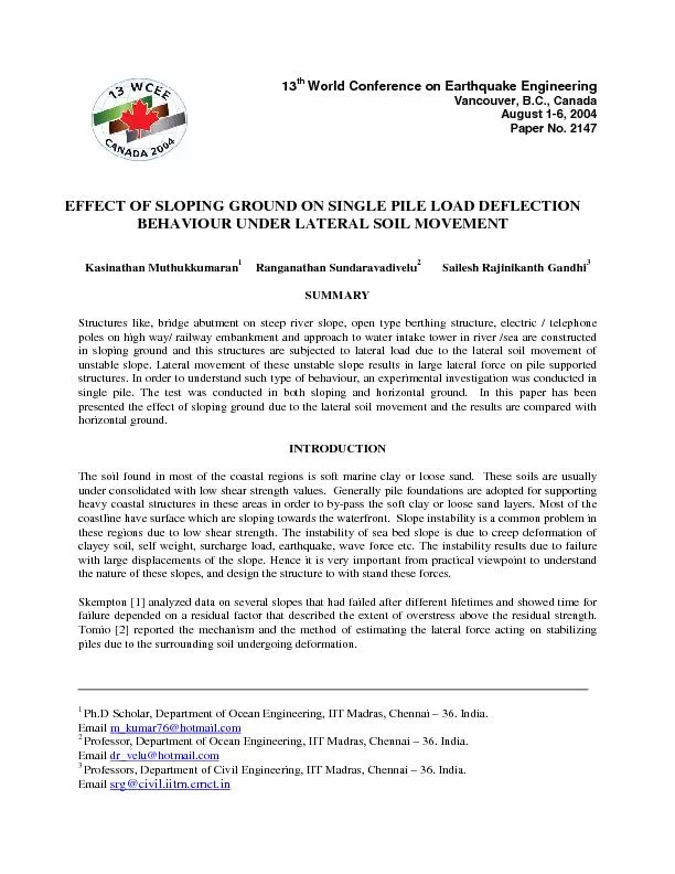


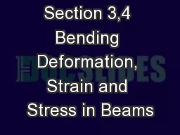

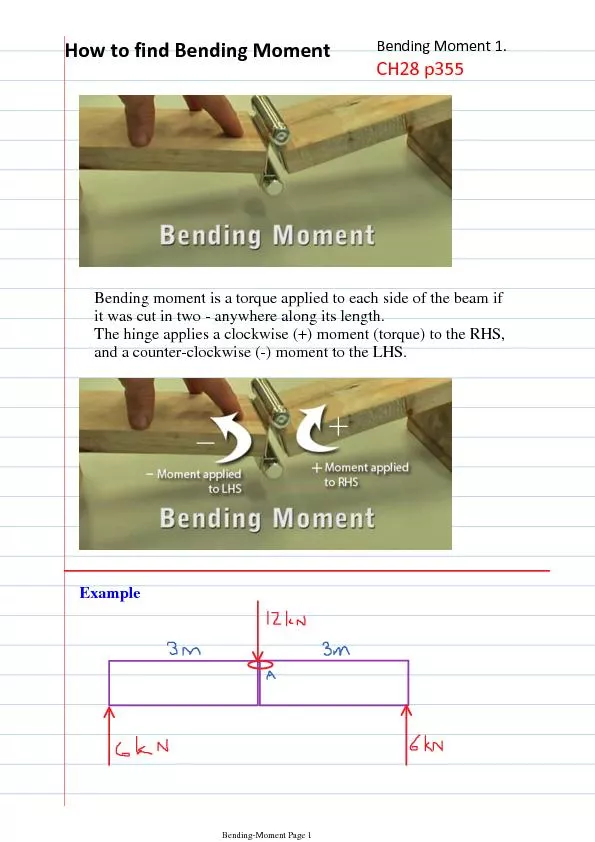


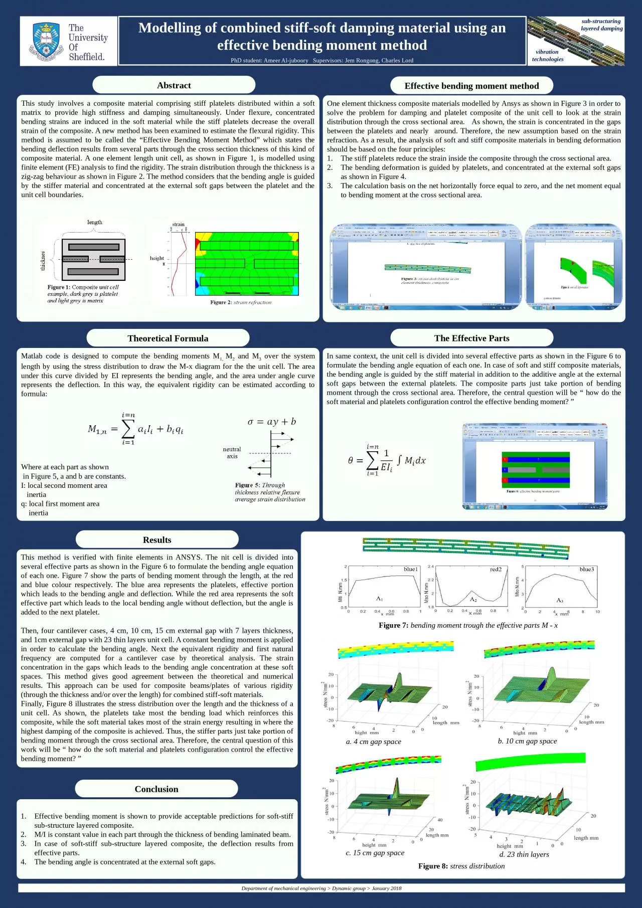
1. Modelling of combined stiff-soft damping material using an effective bending moment methodPhD student: Ameer Al-juboory Supervisors: Jem Rongong, Charles Lordsub-structuring layered dampingThis study involves a composite material comprising stiff platelets distributed within a soft matrix to provide high stiffness and damping simultaneously. Under flexure, concentrated bending strains are induced in the soft material while the stiff platelets decrease the overall strain of the composite. A new method has been examined to estimate the flexural rigidity. This method is assumed to be called the “Effective Bending Moment Method” which states the bending deflection results from several parts through the cross section thickness of this kind of composite material. A one element length unit cell, as shown in Figure 1, is modelled using finite element (FE) analysis to find the rigidity. The strain distribution through the thickness is a zig-zag behaviour as shown in Figure 2. The method considers that the bending angle is guided by the stiffer material and concentrated at the external soft gaps between the platelet and the unit cell boundaries.One element thickness composite materials modelled by Ansys as shown in Figure 3 in order to solve the problem for damping and platelet composite of the unit cell to look at the strain distribution through the cross sectional area. As shown, the strain is concentrated in the gaps between the platelets and nearly around. Therefore, the new assumption based on the strain refraction. As a result, the analysis of soft and stiff composite materials in bending deformation should be based on the four principles:The stiff platelets reduce the strain inside the composite through the cross sectional area.The bending deformation is guided by platelets, and concentrated at the external soft gaps as shown in Figure 4.The calculation basis on the net horizontally force equal to zero, and the net moment equal to bending moment at the cross sectional area.This method is verified with finite elements in ANSYS. The nit cell is divided into several effective parts as shown in the Figure 6 to formulate the bending angle equation of each one. Figure 7 show the parts of bending moment through the length, at the red and blue colour respectively. The blue area represents the platelets, effective portion which leads to the bending angle and deflection. While the red area represents the soft effective part which leads to the local bending angle without deflection, but the angle is added to the next platelet. Then, four cantilever cases, 4 cm, 10 cm, 15 cm external gap with 7 layers thickness, and 1cm external gap with 23 thin layers unit cell. A constant bending moment is applied in order to calculate the bending angle. Next the equivalent rigidity and first natural frequency are computed for a cantilever case by theoretical analysis. The strain concentration in the gaps which leads to the bending angle concentration at these soft spaces. This method gives good agreement between the theoretical and numerical results. This approach can be used for composite beams/plates of various rigidity (through the thickness and/or over the length) for combined stiff-soft materials.Finally, Figure 8 illustrates the stress distribution over the length and the thickness of a unit cell. As shown, the platelets take most the bending load which reinforces this composite, while the soft material takes most of the strain energy resulting in where the highest damping of the composite is achieved. Thus, the stiffer parts just take portion of bending moment through the cross sectional area. Therefore, the central question of this work will be “ how do the soft material and platelets configuration control the effective bending moment? ”Effective bending moment is shown to provide acceptable predictions for soft-stiff sub-structure layered composite.M/I is constant value in each part through the thickness of bending laminated beam.In case of soft-stiff sub-structure layered composite, the deflection results from effective parts.The bending angle is concentrated at the external soft gaps.Matlab code is designed to compute the bending moments M1, M2 and M3 over the system length by using the stress distribution to draw the M-x diagram for the the unit cell. The area under this curve divided by EI represents the bending angle, and the area under angle curve represents the deflection. In this way, the equivalent rigidity can be estimated according to formula: Where at each part as shown in Figure 5, a and b are constants.I: local second moment area inertiaq: local first moment area inertiaIn same context, the unit cell is divided into several effective parts as shown in the Figure 6 to formulate the bending angle equation of each one. In case of soft and stiff composite materials, the bending angle is guided by the stiff material in addition to the additive angle at the external soft gaps between the external platelets. The composite parts just take portion of bending moment through the cross sectional area. Therefore, the central question will be “ how do the soft material and platelets configuration control the effective bending moment? ”vibration technologiesa. 4 cm gap spaceEffective bending moment methodAbstractThe Effective PartsDepartment of mechanical engineering > Dynamic group > January 2018b. 10 cm gap spaceResultsConclusionc. 15 cm gap spaced. 23 thin layersFigure 8: stress distributionFigure 7: bending moment trough the effective parts M - xTheoretical Formula