

r TOP SLAB RFINFOACING RAN R BAR BAR OF l4 4R 145VP1 j 1LpffR 84 pTAPER ALL YALLS b366UlOl8lO Y W NOTE IO L WVERT SECTION 0REAtl Of DEPnATMENT Of PUBLIC WORKS CATCH BASIN NO 62 PREC ID: 899603
Download Pdf The PPT/PDF document "Y2 DIA 04R INSERT0 CAST INIECRAL YInI WL..." is the property of its rightful owner. Permission is granted to download and print the materials on this web site for personal, non-commercial use only, and to display it on your personal computer provided you do not modify the materials and that you retain all copyright notices contained in the materials. By downloading content from our website, you accept the terms of this agreement.


1 r Y2 DIA. 04R INSERT@~-0. CAST INIECRAL
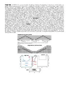
r Y2 DIA. 04R INSERT@~-0. CAST INIECRAL YInI WLEC SECTION. FORMED AS SMJWN TAPERED GRADE RWG m--p TOP SLAB RFINFOACING RAN - R BAR BAR- OF l 4 4R ‘VP1 _ _. _..__.: j (1/L;pf~~;fR 84~~ p-TAPER ALL YALLS ! b3,-6-.6--UlO/l8lO Y W, NOTE IO. L WVERT SECTION ---. 0REAtl Of DEPnATMENT Of PUBLIC WORKS CATCH BASIN NO. 62- PRECAST CITY OF LOIANIXLES STANDARD PLAN -- c-zc;3-n .-- WFLRLMCES -- “cLC”oCIKw -----------m-- --, ---. - .- _-_mk,_ ___ YAW 1 INOEl NUYUf R .--be PLIN TYPICAL JOINT DLTAU. TRANSITtDN SECTION OETAL Y S l 3 BARS 0 EACH NOTE 1 RClNfUKLYENT STEEL EN0 ISLE TRANSITION SIIOWN SHILL APPLY TO GluM SECTION ON SW. NO.11 .niNor ONLY. 1 -1 ADJUSTlN9 SCREW SLOTS -_I CLASS ‘’ NONTAN HSYY FACE .I-AN0 8'GRAOE RNC SHALL BE REWFWCE WITH IWOe GA WIR HOOPS TIED WITH N 14 9AGt WIRE. I’ ac. sEE NOTE. ‘MTERNArE CROSS :lfto 9ENT TO DOT1 S rEEL INSERT OUII. STEEL BAR. ypE0 ON ONE -- ORlLL AN0 ~ALVAMZEO STEEL %2 FOR S/9OlA I I/P= ~~~~~~ SET . PROTECTIDN BAR DETAIL - I-b- -21 I IA CASE I /-INSlCE FACE L/6- MA. THREAOEO PIPE SLEEVE 9’ LONG. WLOEO TO 99’ NUT At40 CAST NTEGRAL wlTti IILET SECTION. CLASS ‘C-MORTAR A ADJUSTING SCREW DETAIL NOTE‘ ULOWAFnE OFFSET 9ETWLEN SECTIONS IS u9-INCtlES c- 2- o-4 NvERT $E,..I~ ,%-d OlMEN9IoHS TYFlCAL AS I EACEPT AS DETAILED HEREON I k CASE 2 fLEVATIOY INVERT SECTIONS l-l-7 CASE 3 --- __.__----.--.- 5TANQARD PLAN NO. S-362-O I -----_ Fii .akOLx -i~-/iiiET 2 .” 4 SHEETS __-_-__- ---- STEEL LIST - ITEM AND LENGTH OUANTITY .- A-BARS “3 deformed bars, _.._ ._. __. 3’ - 2” Long 14 ______.. _.. ._ _ . ____--__-.__.-- _ . B - BARi .__._-____ *3 deformed bar;. 7- 7” Long 4 _. __.-. ___ -..-- --.--.--- . C - BARi ---- __ _L ‘-y3 deformed bars O”~tO” Long 2 - ______.-___ -. --.- --~- _..... . 0 - enis ____---- - ?. .____..__--. -. tt3 deformed 6 __. __--_
2 .._._ bars, 2. Lop9 .___ ____ .._. _._
.._._ bars, 2. Lop9 .___ ____ .._. _.__.._. -- ..- PERIMETER BARS a3 deformed bars, _ Vor ias 6 -TkANS SECTION .__ .___-. . .-.-- - ._.. - _- __._ _ ._ ___ ___-_.e.-.-- RADIAL BARS _. _- ‘3 deformed bwi.,. _ Y!!!!E_____________ ___ !!iL-_ VERildAL AARS “.” i3_d$formed1_bo_!a,_.0-l0 y’ Long 2 ._-._ _ . .._ .- ._. _ ._.._ ______. INVERT SECT!ON __. . VERTICAL BAAS .____ .._ . ..--._ --_.___. _.-me_-.. .__.-_- ---.I_- 83 deformed bars _._.__. . . .- ____. .._._ __ r-2 k” Lonp . __. ____ ?. .- _-___ --- 2 Each Openinq -- -. I+ plam @vonized protection bar See Notes __-. _. .._--.. -- e-m See Notes _--.-- . 314” cb @aIn golvr%ed steps _. . _ . ..- - . _ -_._____-.--__-- Inlet Steel Plale with 3 each !2”4 Anchors I(See Detail) _._ .._._.. - _ .-.__e.- -... -_ _.-m-e------ em Manhole Frame and Cover Set t 5ANO 5Luww MIX On-. LEAN CONCRETL UNOER GUTTER TO LlYlr 5ETlLEYLNT. WALL OF EXCAvAlnJN- MOOlFlEO YONULlTHlC PER ST0 PL 12* IO’ LONG PLACED PHWR 10 CONSlRUClI~~G uwoLITHic C4mNtcllOf~ tryp). _I .t’ _. ~_.___. TYPICAL SECTION CONNECTION AND BEDDING DETALS SECTION B-B NOTES FOR CATCH t3AStN ho.62 (PRECAST) 1. Catch Basin No. 6z moy be mstatled In lieu of Catch Basin No. 39 when the curb face is tO-mher or less the V-dimenston shown on the project drowlngs is equal to or larger than the minimum shown hereon. 2. Inlet Steel shall be fobricotod from %“x 14” Umverrol Mill Plate 3. Protetiian Bar 1 and gotvonired. and a. When the curb face exceeds 94 -inches, a I-Inch dlametar plain be placed horizontally across the opening of the basln. b. One-Inch dwuneler galvanized steel Inserts for the protection bar, equal, shall be cost in each sidewall of the Inlet Section. round golvanired steel protection bar Burke High Tensile Threaded Insert or c The gotvomred steel pipe sleeve sholt be mstolled ot the downslreom end of the catch bosm opening. The brass sock
3 et set screw shot1 not be visible in o f
et set screw shot1 not be visible in o frontal view of the, catch basin openmg. 4.&ttter Oaoresslon shall be constructed In occordunce with Ihe detail for warped gulter per Standard Plan B-3746 unless otherwise specified S.lnvrrt Section Floor shall be gtven a steel trowel finlsh. Where conrlruction methods do not permit lrowellmp Class 658-B-3750 concrete shall be used. Invert shall be sloped toward the outlel for Cose I, and loword Ihr! flow lnes for Cases 2 ond 3. Thr moximum dtfference in elevation between flow tines 0r.d the edge of the floor shalt not exceed 3-inches. STANDARD PLAN ~0.S-36~0 --- VAJLI INrJfX NUUIER 8.5eOT SHEET 3 OF 4 SliEElS r NOTES FOR CATCH BASIN NO. 62 CONTINUED (PRECAST 1 6.Qncre& for the precast sections sholl be Closs 564-B-3250. When the basin is to be assembled within the Itmits of o proposed sldewolk, the top 2(/z-ktches of the basin shall be poured monolllhic wlth the sldewolh usinq the some class of concrete OS the sldewolk ond shall conform In slope, qrode, Color, finish and scoring to existing or proposed walk odjocent to the bosln. 7. Standard Manhole Frame ond Covy per Standard Plan E-2169 shall be placed ot grade Prior t0 POUriRI the catch basin top slob and shall be located OS shown herein. lnslall Manhole Cover LOCkitTJ Device per Stondord B-3233. 8. Dimension$I Mtnrmum V 46” 4-3” - ___ Conneclor Pipe Diometer 16” &I: unless otherwtse spectfied !GO-9” unless otherwise specified See Catch Basin Inlet Detail on Sheet No. I Tn=O-I ?e’ unless otherwtss 1 specified I 9. Joints of Inlet Section, Tronsition Section, Grade Rings, and Invert Sectlon shall be filled wlth Class “C” mortor and neatly pointed on the inrlde of basin. IO.Curvotur~ of the Inlet Section sidewalls shall be formed by curved forms ond shall not be mode by plostertnq. II.Junctlok of Invert Section ond connector plpefs) shall be fllled wlth Gloss “C” mortar. Inlerlor surface the c
4 onnection shall be smooth, clea, ond fre
onnection shall be smooth, clea, ond free from pockets ond protuberancea. 12. Precast section shall have handlinq devices to provide mechonicol placement of the secttons. The Inlet Section shall hove o Superior Concrete Accessortes’ I”x 3 k” Type “S” Coil or equol centered on the exterior of each sidewoll. The Tronsrtion and Invert Sections sholl hove slots integrally cost in the interior walls for lifting hors of 13. Alianment 1 The top frontul edge of thr Inlet Section sholl be allqned with the top frontol edge of the odjocent curb. 14.Stopc ore required l2-Inches apart when “V” is qrrotrr than 4 foot 6 Inches. The top step shall be e-inches below the sofftt and 2 kr-x~hes from the wall. Only one step IFInches from the bottom is required for “V” less thun 4 feet 6 inches. Steps shall be 4-bend, %-inch round qolvonired steel, l4-lnchee wide, with IO- inch tegst Alhombro Foundry Componys Step No. A-3309 cr equal. The steps shall be 6-Inches from the wall of the basln, with the eaceptlon of the top step OS obove. lnstoll steps In bosin ~011 in I- inch drilled holes and grout. 15. Anchor@ shall be &-inch round sleel anchor? or Nelson H4F. Hood Anchors, or equal, electrtcolly welded, I&- inch in diomeler by 6-inches long. 16. Beddinq Material for the catch basin or any material conformtnq to the Standard Specificotton requtrements for select moterhl for base cmd shdl be spread to a minimum depth of 6-inches over the bottom of the excovotion. Beddinq for the inlet ond outlet pipes shall be Closs 470-B-2000 concrete poured between catch basin per detail on Sheet 3. 17. Epoxy that Is opproved by the Enqineer sholl be placed on surfaces of Inlet 18. Monollthlc Connectton shall be tied to catch basin with ‘h-inch diameter by woll of excovotion ond wall of Section before plocinq gutter. d-inch long foundation bolts. STANDARD PLAN NO. S-362-O I VAULr lkOER NUYUCR n-Z407 I SHEET 4 OF 4 SWEE