
May 2018 Djordje Tujkovic et al Facebook Slide 1 Name Affiliation Address Phone Email Djordje Tujkovic Facebook 1 Hacker Way Menlo Park CA 94025 djordjetfbcom Alireza Mehrabani ID: 780745
Download The PPT/PDF document "Adjacent Channel Rejection Requirement" is the property of its rightful owner. Permission is granted to download and print the materials on this web site for personal, non-commercial use only, and to display it on your personal computer provided you do not modify the materials and that you retain all copyright notices contained in the materials. By downloading content from our website, you accept the terms of this agreement.


Slide1
Adjacent Channel Rejection Requirement
May 2018
Djordje Tujkovic et al., Facebook
Slide 1
Name
Affiliation
Address
Phone
Email
Djordje Tujkovic
Facebook
1 Hacker
Way
Menlo Park, CA 94025
djordjet@fb.com
Alireza Mehrabani
tarighat@fb.com
Krishna Gomadam
kgomadam@fb.com
Nabeel Ahmed
nabeel@fb.com
Payam Torab
ptorab@fb.com
Nikolas
Olaziregi
Nokia
Copernicuslaan
50, 2018 Antwerp, Belgium
nikolas.olaziregi@nokia.com
Michael Grigat
Deutsche Telekom
Deutsche-Telekom-
Allee
7, 64372 Darmstadt, Germany
m.grigat@telekom.de
Slide2Background, OutlineDMG (and EDMG) are the only 802.11 PHYs that have not specified Adjacent Channel Rejection (ACR) requirements
In this contribution,
We present a simulation model and results for DMGExample specifications for adjacent channel rejection for DMG
Run two straw polls for DMG and EDMG
Slide
2
Djordje Tujkovic, Facebook
May 2018
Slide3Key Components Impacting ACI RejectionLNA non-linearity
Analog baseband low-pass filter (LPF)ADC sampling rate
Digital low-pass filter and/or raised-cosine filter
Slide 3
Djordje Tujkovic, Facebook
May 2018
Analog BB-LPF
ADC
Digital RRC-LPF
LNA
Slide4Key Components Impacting ACI Rejection (DMG)Example simulation parameters
LNA IP1dB: -33dBmLNA NF: 9dB
Analog LPF: 5th order Butterworth, cut-off (-3dB) frequency: 1.3GHz, input referred SNR of 35dB
ADC sampling rate: 2x1.76GHz=3.52GHzRaised cosine filter: 0.25 roll-off, 12-tap
Frequency offset between target and adjacent waveforms: -40ppm
In addition to above explicit contributors to RX EVM, an implementation loss of 3dB and RX EVM floor of 24dB are included.
Slide
4
Djordje Tujkovic, Facebook
May 2018
Analog BB-LPF
ADC
Digital RRC-LPF
LNA
Other Losses
Slide5DMG Baseline simulation (no ACI)May 2018
Djordje Tujkovic, Facebook
Slide 5
Slide6Baseline Simulation: MCS9 without ACIMay 2018
Djordje Tujkovic, Facebook
Slide 6
EVM: -21.9dB
Sig Power: -59dBm
Noise Power: -81dBm
Analog BB-LPF
ADC
Digital RRC-LPF
LNA
Other Losses
EVM: -13.5dB
EVM: -13.3dB
EVM: -13.3dB
EVM: -9.9dB
~2.5dB margin to SNR requirement
EVM: -13.3dB
Slide7Baseline Simulation: MCS9 without ACI
May 2018
Djordje Tujkovic, Facebook
Slide
7
Analog BB-LPF
ADC
Digital RRC-LPF
LNA
Other Losses
EVM: -21.9dB
Sig Power: -59dBm
Noise Power: -81dBm
EVM: -13.5dB
EVM: -13.3dB
EVM: -13.3dB
EVM: -9.9dB
EVM: -13.3dB
35dB
Slide8Baseline Simulation: MCS9 without ACIMay 2018
Djordje Tujkovic, Facebook
Slide 8
Analog BB-LPF
ADC
Digital RRC-LPF
LNA
Other Losses
Analog LPF NF
dominates aliased in-band noise
EVM: -21.9dB
Sig Power: -59dBm
Noise Power: -81dBm
EVM: -13.5dB
EVM: -13.3dB
EVM: -13.3dB
EVM: -9.9dB
EVM: -13.3dB
Slide9ACI Rejection simulationMay 2018
Djordje Tujkovic, Facebook
Slide 9
Slide10ACI Rejection Simulation: MCS9May 2018
Djordje Tujkovic, Facebook
Slide 10
EVM: -12.9dB
Sig Power: -56dBm
ACI Power: -49dBm
Noise Power: -81dBm
Analog BB-LPF
ADC
Digital RRC-LPF
LNA
Other Losses
EVM: -11.5dB
EVM: -11.3dB
EVM: -11.1dB
EVM: -7.9dB
~0.5dB margin to SNR requirement
EVM: -11.1dB
Slide11ACI Rejection Simulation: MCS9
May 2018
Djordje Tujkovic, Facebook
Slide
11
Analog BB-LPF
ADC
Digital RRC-LPF
LNA
Other Losses
EVM: -12.9dB
Sig Power: -56dBm
ACI Power: -49dBm
Noise Power: -81dBm
EVM: -11.5dB
EVM: -11.3dB
EVM: -11.1dB
EVM: -7.9dB
EVM: -11.1dB
29dB
Slide12ACI Rejection Simulation: MCS9May 2018
Djordje Tujkovic, Facebook
Slide 12
Analog BB-LPF
ADC
Digital RRC-LPF
LNA
Other Losses
EVM: -12.9dB
Sig Power: -56dBm
ACI Power: -49dBm
Noise Power: -81dBm
EVM: -11.5dB
EVM: -11.3dB
EVM: -11.1dB
EVM: -7.9dB
EVM: -11.1dB
Elevated Aliased In-Band Interference
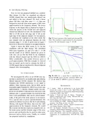
Slide13RX EVM vs. ACI Power: MCS9May 2018
Djordje Tujkovic, Facebook
Slide 13
Simulation parameters
LNA IP1dB: -33dBm
LNA NF: 9dB
Analog LPF: 5
th
order Butterworth, cut-off (-3dB) frequency: 1.3GHz, input referred SNR of 35dB
ADC sampling rate: 2x1.76GHz=3.52GHz
Raised cosine filter: 0.25 roll-off, 12-tap
Frequency offset between target and adjacent waveforms: -40ppm
Additional implementation loss: 3dB
RX EVM floor: 24dB
Target: MCS9 @ -56dBm
(3dB above sensitivity)
Observation
Considering target SNR of ~7.5dB for MCS9 decoding, ACI level of
-49dBm
can be rejected (
+7dBr
)
MCS9 Requirement
Slide14RX EVM vs. ACI Power: MCS12
May 2018
Djordje Tujkovic, Facebook
Slide 14
Simulation parameters
LNA IP1dB: -33dBm
LNA NF: 9dB
Analog LPF: 5
th
order Butterworth, cut-off (-3dB) frequency: 1.3GHz, input referred SNR of 35dB
ADC sampling rate: 2x1.76GHz=3.52GHz
Raised cosine filter: 0.25 roll-off, 12-tap
Frequency offset between target and adjacent waveforms: -40ppm
Additional implementation loss: 3dB
RX EVM floor: 24dB
Target: MCS12 @ -50dBm
(3dB above sensitivity)
Observation
Considering target SNR of ~13dB for MCS9 decoding, ACI level of
-49dBm
can be rejected (
+1dBr
)
MCS12 Requirement
Slide15Dependency on Key Parameters (MCS9)May 2018
Djordje Tujkovic, Facebook
Slide 15
MCS9 Requirement
MCS9 Requirement
Analog LPF:
5
th
order Butterworth, cut-off freq.: 1.3GHz
ADC sampling rate: 2x1.76GHz=
3.52GHz
Analog LPF:
3
rd
order Butterworth, cut-off freq.: 1.0GHz
ADC sampling rate: 1.5x1.76GHz=
2.64GHz
Slide16Example Adjacent Channel Rejection SpecsMay 2018
Djordje Tujkovic, Facebook
Slide 16
MCS
Adjacent
channel rejection (
dBr
)
0
1
2
3
4
5
6
+10
7
8
+8
9
+6
1011
12
-9
Analog LPF:
3
rd
order Butterworth, cut-off freq.: 1.0GHz
ADC sampling rate: 1.5x1.76GHz=
2.64GHz
MCS
Adjacent
channel rejection (
dBr
)
0
1
2
3
4
5
6
+12
7
8
+9
9
+7
10
11
12
-1
Analog LPF:
5
th
order Butterworth, cut-off freq.: 1.3GHz
ADC sampling rate: 2x1.76GHz=
3.52GHz
Example 1
Example 2
Slide17Adjacent Channel Rejection Specification Framework Starting with DMG, i.e., a Clause 20 section (see the straw poll)
EDMG requirements added later in Clause 30Language similar to other PHYs (except 1% PER)
“Adjacent channel rejection is measured by setting the desired signal’s strength 3dB above the IEEE MCS-dependent sensitivity, and raising the interfering signal power until 1% PER for the PSDU length of 4096 octets. The difference in power between the signals in the interfering channel and the desired channel is the corresponding adjacent channel rejection. The center frequency of the adjacent channel is 2.16 GHz away from the center frequency of the desired channel.”
Interfering signal assumed to be a valid
DMG signal
Slide
17
Djordje Tujkovic, Facebook
May 2018
Slide18Straw poll 1 – Adjacent channel rejection requirementsDo you agree with having ACR requirements for TDD-capable DMG devices?
Slide
18
Djordje Tujkovic et al.
May 2018
Mandatory (“shall”) for
TDD-capable DMG devices
Recommended (“should”) for
TDD-capable DMG devices
Yes:
No:
Abstain:
Slide19Straw poll 2 – Adjacent channel rejection requirementsDo you agree with having Mandatory ACR requirements for EDMG devices?
Yes:
No:
Abstain:
Slide
19
Djordje Tujkovic et al.
May 2018
Slide20backupMay 2018
Djordje Tujkovic, Facebook
Slide 20
Slide21Receiver Tolerance to High Input Power (1/2)802.11ad spec already mandates receivers to decode a signal arriving at 10microwatt/cm
2, with same performance as sensitivity level.Input power at single LNA input
10microwatt/cm2 = -20dBm/cm2
Antenna spacing (half wavelength) ~ 2.5mm~16 elements within 1cm2
Power received per antenna ~ -20-10*log10(16)=-32dBm
Considering 2dB loss from antenna to RFIC port,
power at LNA input ~-34dBm
Slide
21
Djordje Tujkovic, Facebook
May 2018
Slide22Receiver Tolerance to High Input Power (2/2)Let’s use the same receiver model in this contribution to evaluate this requirement for MCS12 (no ACI)
Slide
22
Djordje Tujkovic, Facebook
May 2018
Analog BB-LPF
ADC
Digital RRC-LPF
LNA
Other Losses
EVM: -27.7dB
Sig Power: -34.1dBm
Noise Power: -81dBm
EVM: -23.5dB
EVM: -18.0dB
EVM: -17.8dB
EVM: -13.9dB
EVM: -17.8dB
LNA Non-linearity impact
Dominated by
LNA non-linearity
~1dB
margin to
SNR requirement for MCS12
Slide23PA Model to Create 802.11ad MaskPA model is reused from 11ad evaluation methodology document.
Rapp model with following parameters is used:g=4.650,
Asat=0.580, s=0.810, alpha=2560, beta=0.114, q1=2.4, q2=2.3
Slide 23
Djordje Tujkovic, Facebook
May 2018