
1 Electrophoresis is a general term that describe the migration and separation of charge particles under the influence of an electric field The particle may be simple ions complex macromolecules ID: 952899
Download Pdf The PPT/PDF document "ELECTROPHORESIS" is the property of its rightful owner. Permission is granted to download and print the materials on this web site for personal, non-commercial use only, and to display it on your personal computer provided you do not modify the materials and that you retain all copyright notices contained in the materials. By downloading content from our website, you accept the terms of this agreement.


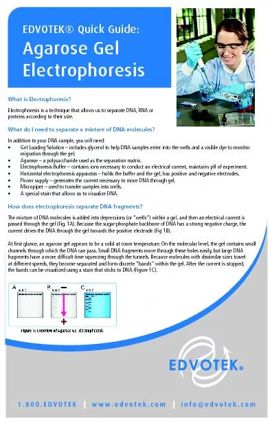
1 ELECTROPHORESIS Electrophoresis is a general term that describe the migration and separation of charge particles under the influence of an electric field. The particle may be simple ions, complex macromolecules and colloids or particulate matter - either living cells such as bacteria or inert material such as oil emulsion, droplet and clay. If a foreign phase which is charge, is subjected to a potential gradient, the foreign phase will migrate throu gh the continuous medium to the cathode or anode according to the sign of charge on the particles. This phenomenon is called electrophoresis. Migration can occur also in a non - uniform alternative current, provided the particles are polarisable, and its tra nsport phenomenon is called dielectrophoresis. Some of the techniques result in complete separation of the component into distinct zone , this is refer red to as zone electrophoresis. Electrophoresis is the most useful separation techniques for the analysis and characterization of complex biological mixture of protein. The analysis of protein mixture was first established by Tiselius in 1937. His separation of serum proteins into four major component are serum albumin , alpha, beta and gama - globulins. Electr ophoresis is to relate the experimentally measurable electrophoretic velocity to move fundamental parameter of ions interactions, charge and structure in the neighbourhood of charge particles or surface. The theory of the electric double layer deals w ith t he se parameters
and is necessitated by the colloidal particle create their own ionic environme nt, being much larger and having a higher charge than small ions. The most useful criterion for classification is whether electrophoresis is carried out in free s olution or non supporting media. Free electrophoresis Techniques are : 1. Tiselius moving - boundary electrophoresis. 2. Microscope electrophoresis. 3. Continuous – flow curtain electrophoresis 4. Electrodecandation and electrophoresis - convection. 5. Column electroph oresis (density and pH gradient electrophoresis ) 6. Force - flow electrophoresis. 2 Tiselius moving - boundary electrophoresis The moving - boundary techniques the first method to demonstrate the great resolving power of electrophoresis . It is an elegant technique in which several logi stic s problems were solved in a most clever ⠀if complicated⤀ way by achieving. ⠀i) initial formation of sharp boundaries ⠀ii) automatic stabilization of boundaries by density gradients ⠀iii⤀ good heat dissi pation and ⠀iv) optical visualization of components during migration. It is embodied in the Tiselius cell, w ith U - shap ed channel of rectangular cross section and optical flat fused glass windows . The cell consists of three sections, which can slide indepen dently of each other on lubricated glass surface as illustrated under figure. Fig. Tiselius electrophoresis cells ⠀a) Initial boundaries position ⠀b⤀ Upon electrophoresis, separation o
f boundary has taken place in the two limbs of the U - shaped cells. 3 The bottom section and one limb of the cell are firs t filled with prote i n, the remainder of the cell in them filled wit h buffer. When an electric fiel d of proper p olarity is established, migration of proteins will cause the initially sharp boun daries to se parate into several sub - boundaries. The greater density of the pr o te i n solution sta bilized it boundaries and prevent convective mixing with the lighter buffer but also prevent comp lete separation of protein com ponents. The component remain overlapping , an d the analy sis is bas ed on the migr ation velocit y of the density boundaries in the ascending and descending limbs f or various theoretical re a son. In the as cending limb s , the leading, fastest protein is moving into a region of higher condu c tivity, which ten d s to slow down the migration velocity. This result in a sharpening of the as cending boundary. The opposite effect is noticed in the descending boundary, where the trailing boundary moves into a region of lower conduc tivity, resulting in a diffusion of it s pattern. Two schlieren systems are available, based on the scanning and by the cylin drical lens camera . B oth depe nd on the deflection of light as it passes through the gradient of i ndex of refraction existing across each bou ndary, and give the easily r ecog nizable pattern as illustrated under figure. 4 In addition, the or i ginal discontinuity of electrolyte concentration
across the boundary cause salt boundaries to appear in the cell, which are not related to the presence of a protein. These two boundaries , denoted on δ in the as cending and \nc in the descending limb, remain relativ ely stationary during electropho resis. The simplified U - tube arrangement s the migration of colloids was followed either by visual colour and turbidity or by ultraviolet light absorption. T hese technique s have been completely d isplaced by schlieren and inter ference optics which gave much better resolution and quantisation of the boundaries. Continuous - flow Curtain Electrophoresis This technique is illustrated in under Figure ⠀A). In this technique electrophoresis is carried out continuously. In this a curtain of filter paper is employed which is immersed in the buffer solution. The sample is applied through an applicator ⠀Sa⤀. The sample is fed to an applicator by a sample reservoi r ⠀S⤀. Two parallel ends of the filter paper are immersed in two 5 electrode compartments in the form of the small ends of the filter paper ⠀fluted form⤀. On application of electric field, the solute particles starts moving under the influence of the potent ial gradients in downward flow of liquid. The components are resolved in different fronts and separated in bottom of the test tube as shown in figure. The electrical field is perpendicular to the flow of buffer and the components are separated, forming a angular pattern. The angle of deflection α
is obtained from the following relation: Tangent α = rate of electrophoretic migration / rate of buffer flow High density Gel electrophoresis It is possible to prepare high density gels with effective pore sizes approaching the dimensions of the protein molecules to be separated. In such gels, small molecules migrate to the bigger m olecule. This results in great enhancement of the resolving power and protein molecules being characterized by differing parameters of size and shape. Basically this separation method uses a column packed with the porous separating medium. Such columns hav e a variety of dimensions but are typically 1 to 3 cm in diameter and 1 to 10 meter long. A number of porous materials have been used: cross - linked polymer, porous gels, ceramic materials and others. A solvent is passed continuously through the column. A s mall amount of material to be separated is introduced at the head of the column, usually as a solution in the same solvent that is being pumped through the column. The retention volume can be expressed by: V R = V M +KV S , where the mobile phase volume V M and the stationary phase volume V S are the void volume and the total pore volume of the packing materials respectively. The distribution constant K depends on the molecular weight of the sample and the pore size of the gel. Small molecules that can ente r into the pores freely have K=1, whereas very large molecules that are completely excluded from all pores have K = 0. Intermediate size molecul
es have access to various portions of the available pore volume and have K values between 1 and 0. Thus 6 large mo lecules move through the column more rapidly than small molecules. Molecular size is associated with the identified by the particular elution volume at which a given molecules emerges. Below figure is a schematic representation of the separation process. Electro decantation And Forced - Flow Electrophoresis : The electro decantation may occur whenever a semi permeable membrane is interposed into the pathway of electrophore ti cally migrating colloids. Semi permeable mem branes, such as parchment paper allow free passage of electrolytes ions but retain coll o ids by their greater particles size. The migrating colloids accumulate; in front of cell membrane where they form a layer of increased concentration. This colloid enriched layer will either decant 7 to the bottom or float to the top; depending on whether the colloid is heavier or lighter than the solvent. Electro decantation is also useful for the purification of certain p rotein fractions; particularly gama - globulin from human serum; where the desired p urified end product. Forced flow electrophoresis is a newer and more versatile technique; capable of similar to those obtained with electro decantation , but applicable also to other electro kinetic membrane processes; such as electro dialysis , electro - osm otic concentration or electro filtration. In its simplest configurati on, it is illustrated under figure. It uti
lized a system of parallel semi permeable membranes e xcept that the filter elements is introduced between each two membra ne separating the intr amembrane spaces into input and output compartments. The colloidal solution to be processed is continuously circulating through the input compartments; and part of the liquid is forced to flow through the filter into the output compartments. The liquid flo wing through the filter is exposed to the electric field, forcing the colloid to migrate in count er current direction. In the above figure t his is 8 shown by the broken & solid arrows, respectively. If the electrophoretic vector is equal to or large than the linear rate of flow in the opposite direction; no charged colloid will be go through the filter. The filter act s also as a frictional boundary bet ween the downward flowing layer of increased colloid density and the up - ward flowing colloid layer. This process independent of the unpredictable element of decantation; and complete control of all operational is possible through appropriate regulation of flow rates. Forced flow electrophoresis has been applicable for large scale water and waste purification through direct removal of colloid impurities. Continuous filtration of algae ; clay, and other gelatinous materials is possible; without any formation o f filter cake, its deposition being prevented by the electric filed. The technique has been also applied to a number of biological processes ; such as blood electrophoresis. Application: Most applicatio
n of electrophoresis are related to the analysis of p roteins in the se rum or other body fluids. For a simple analysis, it is suitable for detection of major components. In clinical medicine, electrophoresis is used for the diagnosis of certain specific diseases, characterized by the presence of abnormal prot eins , either genetically conditioned or induced by the disease. A well - known example of a genetic molecular disease is anaemia , due to abnormal haemoglobin in the red blood cells of the affected individuals. Tiselius moving - boundary electrophoresis is th e method of the choice for the determination of absolute electrophoretic mobility . It is also useful for the study of rapidly interacting protein system and for other similar physicochemical research. Electrodecantation and forced - flow electrophoresis are the only two techniques adoptable for large - scale industrial application. Electrodecantation has been applied to such problem as the creaming of rubber latex and the concentration of Teflon latex. Force - flow electrophoresis is a more versatile and newer t echnique adoptable to a variety of electro kinetic processes such as electrophoretic separation, electrofiltration and electro - osmosis concentration. 9 Reverse Osmosis Osmosis, from the “ Greek ” word for push refers to the passage of a solvent , such as water; through a dense membrane that is permeable to the solvent ,but not the solute ⠀ e.g. inorganic ions⤀. The important aspects of osmosis are ill
ustrated by example in Fig 1. Where the all solution are at 25 0 C. In the init ial condition shown as Fig 1(a⤀ seawater of approximately 3.5 wt% dissolved salt on the left side of the membrane ; while pure water at the same pressure is on the right side. The dense membrane is permeable to water, but not to the dissolved salts. By osm osis, water passes from the right side to the sea water on the left side; causing dilution with respect to dissolved salts. At equilibrium, the condition of Fig 1. ⠀b⤀ is reached, wherein some pure water still resides on the right side and sea water become less concentrated in salts; resides on the left side. The pressure P1 on the left side is now greater than the pressure P2 on the right side, with the difference, π , referred to as the osmotic pressure. Osmosis Reverse osmosis P1 Seawater water Seawater water Water P1 P2 P1 P2 P2 P1= P2
P1 - P2 ≤π P1 - P2 \tZ π ⠀a) ⠀b⤀ ⠀c⤀ Fig.1. Osmosis and Reverse Osmosis phenomena ⠀a⤀ Initial condition ⠀b⤀ At the equilibrium after osmosis ⠀ c⤀ Reverse Osmosis The process of osmosis is not useful as a separation process because the solvent is transferred in the wrong direction; however the direction of transfer of solvent through the membrane can be reverse, as shown in Fig. 1.⠀c⤀ by app lying a pressure P1 on the left side of the membrane, that is higher than the sum of the osmotic pressure and the pressure P2, on the right side that is P1 - P2 \tZ π . Now water in the seawater is transferred to the pure water and the 10 seawater become more conce ntrated in dissolved salts. This phenomenon called reverse osmosis, and can be used to partially remove a solvent from a solute - solvent mixture. ⠀ π is proportional to the solute concentration ⤀. Reverse osmosis is used for separation with solutes up to a molecular weight of about 500. This low molecular weight of the solute has some significant for the performance of the process. To separate particles that are of about the same order of magnitude a micro porous membrane is not suitable. Therefore most reverse osmosis process utilize a homogeneous membrane or an asymmetric membrane with a homogeneous skin. A solution of particles that have a molecular weight of 500 or
less may have a significant osm otic pressure, perhaps as high as 100 atm.; depending on the concentration of the solution. To yield any separation the osmotic pressure difference between the feed solution and the filtrate has to be overcome by an applied hydrostaticpressure, hence sign ificantly higher hydrostatic pressure are required in reverse osmosis process than in ultrafiltration.⠀ The basic difference between reverse osmosis and ultra filtration lies in the size in the solute that is separated from a solvent under the driving forc e of a hydrostatic pressure). When a solution is confined under pressure on one side of a reverse osmosis membrane, the solvent and solute transport rates across the membrane can be approximated by the relationships: Jv = K1/ λ ⠀ ΔP - Δπ) --------- ⠀1⤀ and Js= K2/λ(Cb - Cp) ------------- ⠀2) Where: Jv and Js are the solvent and solute fluxes across the membrane; ΔP is the hydraulic pressure difference between the solution and the product. Δπ is the osmotic pressure difference between two solut ions, Cb is the upstream solute concentration and Cp is the solute concentration in the product. K1 and K2 are the transport coefficients of the membrane to solvent and solute respectively and λ is the effective membrane thickness. We know that, Cp = Js /Jv -------------------- ⠀3) 11 After simultaneous solution of equations 1, 2 and 3 yields: R = ⠀1 - Cp/Cb) X100 = {k1/K2( ΔP - Δπ )} / {1+K1/K2(ΔP - Δπ)} X100 -------- ⠀4⤀ whe
re: R is the Rejection of membrane. It may be clear from equation no. ⠀4⤀ that unlike the ultrafiltration case, the rejection increases with increasing effective pressure difference across the membrane. This is true because the solvent flux is the pressure dependent whereas solute flux is nearly independent of pressure. Application : The most important application for reverse osmosis is the large scale purification of saline water sources. Although reverse osmosis is generally not an economical process for sea water desalination, it can be practical importance in certain area for brack ish water and waste water purification. Reverse osmosis is currently being applicable for several pollution control areas, for example, tertiary treatment of sanitary sewage; purification of acid mine water and concentration of whey streams from the milk and cheese industry. Other use of reverse osmosis, usually on a smaller scale than the desalination of water to produce protable water, include: ⠀i) The treatment of industrial waste water to remove large metal ions, non biodegradable substances and other comp ound of commercial value. ⠀ii⤀ The separation of sulphites and bisulphites from effluents in pulp and paper processes. ⠀iii⤀ The recovery of constituents having food value from waste water in food processing plants, e.g. lactose, lactic acid, sugar and starches. ⠀iv⤀ The dewatering of certain food products such as coffee, soups, tea, milk and tomato juice. ⠀v⤀ The concentration of amino acids and alkaloids. 12
SUBLIMATION Sublimation is the transition from the soli d phase to the gas phase without passing through an intermediate liquid phase. This endothermic phase transition occurs at temperature and pressure below the triple point. Iodine crystal and solidified carbon dioxide are examples of substances that sublima te at room temperature and regular atmospheric pressure. At normal pressure, most chemical compounds and elements passes three different states, solid, liquid and gas at different temperature. The process involved when a solid is vaporized without melting and the vapour(upon cooling⤀ is condensed directly back to the solid state. The initial solid is referred to as the sublimand and the product as the sublimate. The solid will sublime if its vapour pressure reaches atmospheric pressure below the melting poi nts. Line curve AP represents the variation of M.P. with pressure. Line BP represents the variation of boiling points with pressure and line CP represents the condition under which solid and vapour are in equilibrium. The product P at which the vapour pressure curves intersects is known as the triple point and specifies the conditions under which the three state of matter can exist in a 13 state of equilibrium. If the vapour at temperature T 1 and pressure P 1 is cooled to the temperature T 2 , the vapour is p ass first to the liquid state and finally at the melting point to the solid state. On the other hands, if a vapour at pressure P 2 which is below the triple poi
nt pressure, is cooled sufficiently, the vapour will condense directly to the solid state without forming the intermediate liquid phase. Similarly, a solid can be completely vaporized without passing through the liquid state provided the pressure of the vapour is not allowed to exceed the triple point pressure. If the triple point pressure is fairly h igh, it will be easy to establish the conditions necessary for sublimations to occurs. The temperature at which the vapour pressure of the solid equals, atmospheric pressure is frequently referred to as the sublimating points. It is the characteristics of a particular substance as is the boiling point or melting point. Like the boiling points, the subliming point is influenced by the pressure of the other vapour and varies greatly with the pressure in the system. The temperature at which the sublimate fir st becomes noticeable in a given system is often referred to as sublimation temperature. There are two basic approaches to the practical sublimation of the substances : first is Vacuum Vacuum sublimation and second is entrainer sublimation. Vacuum Sublimat ion A technique for purifying solid samples by heating the sample under vacuum. The sample sublimes and the vapour condense as a purified compounds on the cooled surface, leaving the non - volatile residue impurities behinds. It can be operated over a wide range of pressure and temperature and sublimation are readily recoverable. There is a little change with apparatus of this type that substances with similar vapour pressure can be s
uccessively fractionated. To accomplish a fractional sublimation, some deg ree of preferential vaporization and or condensation must be exhibited by the solids. That is those must be pronounced difference in the vapour pressure and sample components at given temperature. 14 With a controlled source of heat, the temperature of t he sublimand still can gradually raised with the collection of successive fraction of sublimate. The rate of sublimation may be quite low if the vapour pressure of the solid is low. Sublimation differs from distillation in that the surface layer of the sol id gradually vaporise, exposing new surface whereas in distillation, a new liquid surface is continually being produced by evaporation, diffusion and convective currents. In order to obtain the maximum rate of sublimation the surface area of the sublimand should be great as possible and the distance between the sublimand and condensing surface should be short. Entrainer Sublimation The second approach to the practical sublimation of substances entrails, the use of an inert gas as a “carrier “or “entrainer ”. with the inert gas moving slowly over the sublimand the partial pressure of the sublimand vapour is swept along(entrained⤀ by the carrier gas. A simple vacuum sublimation frequently can be speeded up by using an entrainer, since the sublimand vapour is moved as rapidly as it is formed from the vicinity of the sublimand. 15 An added advantage to entrainer sublimation techniques is the possibility that solid with some similar vapour pressu
re can be resolved by establishing a temperature gradient along the condenser tube or by fixing the temperature of finite portion of the condenser as illustrated under figure.2. With each successive condenser section held at a lower temperature, the least volatile constituents should condense first etc. resulting in a fractionation. Applications : • Sublimation are used for the separation of volatile crystalline compounds from non - volatile substances and from volatile substances, which do not condense under the condition existing at a given point at the system. • Yield of high purity are usually obtained for naphthalene , anthrancene, benzoic acid, sali cylic acid , camphor, beta - nepth al, steric acid etc. are separated by under normal pressure. 16 • At reduced pressure many more substance can be sublimed. For example. 1 - hydroxy anthraquinone can be separated from 2 - hydroxy anthraquinone by sublimation at 130 o C , subsequently, 2 - hydroxy compound can be sublimed at 180 0 C. • Mixture of benzoic acid can be resolved by sublimation of the acid at 50 0 C . Saccharine sublimes rea dily at 150 0 at the same pressure. • Niobium and tantalum are separated by their halide by used of sublimation techniques. Mixture of Nb 2 O 5 and Ta 2 O 5 are heated with the appropriate aluminium halide a closed tube to convent the oxides to the halides. • Fra ctional vacuum sublimation has proved especially effective in the examination of drugs. 17
ULTRACENTRIFUGATION It is an important tool in biochemical research, which through rapid spinning imposed high centrifugal force on suspended particles, or even molecules in solution, and causes separation of such matter on the basis of differenced in weight . For example, red cells may be separated from plasma of blood, nuclei from mitochondria in cell homogenates and one protein from another in complex mixtures, and also isolation of macromolecules such as DNA, RNA, Lipids etc. Its rotational speed up to 150000 rpm. It is a separation method on the preparative scale for the isolation and purification o f biopolymers, virus and cell pigments. It is generally divided in two classes : 1. Analytical Ultracentrifugation: Used to determine physical properties of solutes or particles. The aim of analytical ultracentrifugation is use to study molecular interaction between macromolecules or to analyse the properties of sedimenting particles such as their apparent molecular weight or sedimentation coefficient. Two kinds of experiment are commonly performed on these instruments: ⠀i) Sedimentation Velocity Experiment: The aim of Sedimentation Velocity Experiment is to interpret the entire time - course of sedimentation and report on the shape and molar mass of the dissolved macromolecules as well as their size distribution. ⠀ii⤀ Sedimentation Equilibrium Expe riment: These are concerned only with the final steady - state of the experiments, where the sedimentation is balanced by diffusion oppos
ing the concentration gradient, resulting in time independent concentration profile. 2. Preparative Ultracentrifugation: The aim of the preparative ultracentrifugation is to isolate and purify of specific particles such as sub cellular organelles . It is to isolate specific particles which can be reused. This is also two types. ⠀i)Differential Ultracentrifugation: it is a comm on procedure in microbiology and cytology used to separate certain organelles from 18 whole cells for further analysis of specific parts of cells. In this process, a tissue sample is first homogenised to break the cell membranes and mixed up to cell contents. The homogenate is then subjected to repeated centrifugation, each time removing the pellets and increasing the centrifugal forces. Finally purification may be done through the equilibrium sedimentation, and the desired layers is extracted for further anal ysis. ⠀ii⤀ Density Gradient Ultracentrifugation: Based on the density difference, there are the two types of density gradient ultracentrifugation under preparative ultracentrifugation such as ZONAL or RATE and ISOPYCNIC. In the case of ZONAL cen trifugation, mixture to be separated is layered on top of the gradient ⠀increasing concentration down the tube⤀.It provide gravitational stability as different species; while in the case of ISOPYCNIC centrifugation, molecules separated on equilibrium posit ion. Not by rates of sedimentation. Each molecule floats or sinks to position where density equals density of CsCl solution. Isopycni
c is encountered in biophysical chemistry and usually in reference to a process of separating particles, sub cellular organ ells or other substances on the basis of their density. It refers to a method where in a density gradient is either preformed or forms during high speed centrifugation, after this gradient to the position having a density matching their own. This technique s is extremely powerful. Preparative ultracentrifuge are available with a wide variety of rotors suitable for a great range of experiment. Most rotors are designed to hold tube that contains the sample. Swinging bucket rotors allow the tubes to hange on hi nges, so the tubes reorient to the horizontal as the rotor initially accelerates. Fixed angle rotors, are made of a single block of metal and hold the tubes in cavities bored at a pre - determined angle, while Zonal rotors are designed to contain a large vol ume of sample in a single central cavity rather than the tubes. Some zonal rotors are capable of dynamic loading and unloading of samples while the rotor is spinning at high strength. 19 ZONE MELTING The gener al term Zone melting denotes a number of similar techniques used for controlling the concentration and distribution of soluble solutes in crystalline materials. The basic concept of the method is illustrated in figure 1. A bar of solid material that contai ns a small amount of impurities is heated at one end by a narrow external source; thus a molten zone is created while other part of the bar remains solid
. Then the heat source is moved along the bar, causing the molten zone to move with the same velocity. During the process the concentration of impurities that have greater solubility in the melt than in the solid increases gradually in the molten zone. The impurities are, therefore, accumulated in the melt and swept to the other end of the bar, where they a re removed. Now zone melting embraces a family of techniques that arise from the concept of moving a zone of one phase through another. This process is not restricted to material that are solid at room temperature and the moving phase can also be vapour or solid. The theory consist of the, distribution coefficient K1 defined as the ratio of the solute concentration in the freezing solid to that in the liquid phase. The value of K depends on the number of factors such as the rate of zone travel, degree of mixing within the zone and freezing conditions. Let us first consider the solute distribution after a single molten zone has pass through an ingot slowly having length l as shown in figure ⠀A⤀. Consequence of a single pass and the molten zone through the i ngot are illustrated in figure ⠀B⤀. The composition of the ingot now varies along its length and can be broken into three distinct parts: 20 ⠀i) in the first parts the solute concentration has been reduced ⠀ii⤀ in the central part the solute concentration is unchang ed and ⠀iii⤀ in the final part the solute c oncentration had been increased After the zone has advanced a short distance, a freezing inter
face forms at x =o The solute concentration in the newly frozen solid will be KCo. Simultaneous with the deposition of solu te in the freezing melt, the melting interface at x = l is taking in a solute concentration of Co. Thus as the zone advances through the ingot the concentration of solute in the zone builds up, resulting in the freezing out of higher concentration of solut es. This enrichment of the zone continues at a decreasing rate until the concentration of the solute in the zone is equivalent to Co/K. From this point on, the amount of solute entering and leaving the molten zone at the two interface is equal and the con centration of solute in the newly frozen ingot remains constant until the melting interface reaches the end of the ingot. Further movement of the zone merely decrease the length of the zone, causing the solute concentration to rise sharply in the melt and the solid. Detailed calculations shows that there is an advantage in using a relatively long molten zone in the early passes the bring about a rapid movement of impurity and a short zone in the latter passes to bring about a greater degree of purification. Ratios of column length to zone length of 10 or greater in the later stages generally permits a good final purification to be achieved . The number of passage of the zone is necessary to produced a concentration distribution approximate to the ultimate one i.e. n →∞ depends upon the value of Kd and on the ratio of column length of zone length ⠀under figure⤀ where Kd is 0.2, and if the ratio of column length
to zone length is 10 ,Ten passes will bringe about a relative impurity concentration of o nly 2x10 - 5 at one end and 10 - fold increase at the other. If nothing is known about the system, it is usually reasonable to try between 10 and 20 passes. 21 Apparatus: - Zone - refining apparatus can be broken down into a group of essential components; namel y, heaters, travel mechanism stirrers and sample containers. 1. The heating devices are short resistance coils; wound about the sample or sample tube. The device is simple and expensive; but it means that the sample container will be hotter than the zone, whi ch increases the possibility of contamination. Induction heating eliminates this difficulty by generating the heat within the charge itself; but the equipment is bulky and expensive. Over techniques used in heating include direct contact of sample or conta iner with flames, passage of an electric current through the charge, electron bombardment, radiant heating and heat transfer with fluids. 2. In certain case it may be more desirable to move one than the other. The chief requirement in that the molten is fairl y ⠀clearly⤀ steady and move travel of the other end of one inches per hour. The movement of the zone must be relatively slow to allow crystal formation without the 22 occlusion of liquid. Many kinds of drive mechanism have been employed. Lead screw drive, cor d and drum drive, cane drive, direct motor drive etc. 3. The efficiency of zone refining is greatly increased if the molten zone is vigorously stirr
ed. Convection current within the zone are usually adequate for stirring purpose, particularly with organic m aterial, but forced convection is sometimes desirable. Induction heating produces convection currents and so do supersonic vibrations. Magnet stirring can be achieved in ingots, if an electrical current is passed through the charge axially ⠀axis) and a mag netic field is impressed near one end of the molten zone, normal to the sample axis. 4. The selection of a container for the charge in zone refining is largely a matter for the individual researcher to decide. It is essential only that the container not contaminated the sample and that the longitudinal thermal conductance of the container be less than or comparable to that of the sample material. Materials that have found widespread application are Pyrex - glass, fused silica, graphite, alumina and magnesia . The most common shape for the container or ingot is cylindrical cross - sectional shapes have been circular; ring shaped and rectangular. Lengthwise, the charges have been formed into circular, Spiral and helical forms. The helical form has a distinct in a dvantage in that a long charge can be compressed into a small space and a single heater can produce all the ions. As the helical coil is slowly rotated, the molten zone at the top of each turn moves along the length of the tubing; passing through the solid phase in each turn. 23 The most popular form of the container is the floating zone techniques where the molten zone is held in place by its own surface tension as i
ndicated under figure. For e.g. if the centre of the floating zone can be made lie above, the induction coil used for heating the zone, the levitate action that arises from the repulsion between induced and inducing current will help to support the zone. 24 Application: - This technique is largely applicable to the purification of germanium and s ilica for the transistor industry. Six zone passes through the purest commercially available germanium reduced the conductivity producing impurities to less than 1 in 10 10 atoms of germanium. “Sehwob and Wickers’’ of the national bureau of standards appli ed the principle to the purification of benzoic acid. The technique involved the slow lowering of a cylindrical cell of the fused compound through a heating coil in such a way that freezing began at the bottom and progressed upward through the cell. An out standing example of purification of organics by zone melting is the treatment of naphthalene. Wolf and Deutsch claim that the main impurity in anthracene, in naphthalene was reduced to less than one part in 10 6 by lowering a test tube and the substance thr ough a narrow ring - shaped furnace at the rate of 1 cm/hour. Zone melting has important uses other than purification. It can be used for zone levelling, namely the uniform distribution of impurities through the charge. It can make precisely controlled disc ontinuities in impurity concentrations and it can be used in special case for concentrating impurities unobservable by conventional procedure prior to their analysi