/
Pipeline Corrosion Control Issues and Technology Pipeline Corrosion Control Issues and Technology

Pipeline Corrosion Control Issues and Technology - PowerPoint Presentation

brooke
brooke . @brooke
Follow
65 views
Uploaded On 2023-10-27

Pipeline Corrosion Control Issues and Technology - PPT Presentation

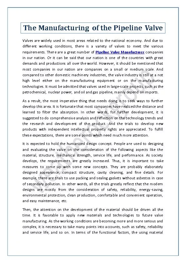
Lyndon Opdyke Chief Corrosion Technician Alliant Energy Corporation Topics of Discussion Equipment and Technology Improvements to Monitoring and Testing Equipment Stray Current Corrosion Types and Case ID: 1025349

soil current cathodic stray current soil stray cathodic interference protection pipe pipeline study currentscase piping shielding system currents data

Share:

Link:

Embed:

Download Presentation from below link

Download Presentation The PPT/PDF document "Pipeline Corrosion Control Issues and Te..." is the property of its rightful owner. Permission is granted to download and print the materials on this web site for personal, non-commercial use only, and to display it on your personal computer provided you do not modify the materials and that you retain all copyright notices contained in the materials. By downloading content from our website, you accept the terms of this agreement.


Presentation Transcript

1. Pipeline Corrosion Control Issues and TechnologyLyndon Opdyke Chief Corrosion TechnicianAlliant Energy Corporation

2. Topics of DiscussionEquipment and Technology Improvements to Monitoring and Testing Equipment.Stray Current Corrosion Types and Case Studies.Interference Bonds.Shielding in Cathodic Protection Systems.Soil Types and How They Can Affect Corrosion Rates.2

3. Technological ImprovementsInstrument capabilities and features.Protection from obsolescence.Better battery performance.Environmental protection to better perform in adverse conditions.3

4. Voltmeters - Fluke 287 & 289Firmware and software upgrades to keep the instrument current.Simplified Min/Max function.Measures AC and DC at same time.High performance 5 ½ digit meter.Powerful data logging ability.4

5. Pipe Locators – Radiodetection PCMxDoes peak and null locating at the same time.Will characterize corrosion control currents on a pipeline.Better pipe depth locating abilities.Integrated GPS and data logging.Can perform ACCA and ACVG surveys in one pass.5

6. Radiodetection – Stray Current MapperIt has multiple magnetometers in the bar and can measure low level interference currents.It is a data logging device.It would be used in conjunction with an interrupter to identify a current source.6

7. Close Interval Potential Survey EquipmentData logger.Back pack or hip pack wire dispenser and measurerTwo calibrated and matched reference cells with extension poles.Computer and software to upload data and display the results.Available from M.C. Miller, Cathodic Technology, and others.7

8. Soil Resistivity MetersMeasure resistance using 67 hz AC to minimize innacuracy from stray earth currents.Ideally suited for doing Wenner four pin method of testing soil resitivity.Comes in ruggedized weather proof case.Available from several different vendors including M.C. Miller and Tinker & Rasor.8

9. Stray Currents9Can be caused by electric traction trains, welding operations, cathodic protection systems, and Telluric currents from solar activity.Cathodic protection induced stray currents usually come from a rectifier ground bed system but can be caused by sacrificial cathodic systems as well.Stray currents can cause significant damage to pipelines and other structures.

10. Stray Current – Weld End Insulating CouplingNote the continuity strap on the right end of the coupling10

11. Weld End Insulating CouplingLeft End ViewNote the sharp features of the formed end of the outer section of the coupling.Note also the apparent good condition of the pipe in the vicinity of the light colored insulating material.11

12. Weld End Insulating CouplingRight End ViewNote the destruction of the sharp features at the end of the outer part of the coupling due to corrosion.Note the presence of the white calcareous deposits on the pipe near the coupling.This indicates ionic current flow from the outer sleeve to the pipe.12

13. Stray Current – Weld End Insulating Coupling13The failure of the coupling was due initially to a longitudinal force that pulled one of the pipe nipples in the coupling out far enough to initiate a leak.This movement also broke the continuity strip free from the pipe nipple and electrically isolating the outer part of the coupling from either end of the coupling.The outer part of the coupling was picking up current from an unknown source and discharging the current on the end with the continuity strip while the pipe on that end was afforded a level of cathodic protection as evidenced by the calcareous deposits.

14. Stray Current – Interference CurrentsSources 14Interference currents can be caused by several different sources including DC welding operations, electric traction trains, mining operations, certain industrial applications involving DC motors, HV DC transmission lines, and cathodic protection systems.Interference will by definition cause some kind of current flow in a piping system that may be static in nature or dynamic as would be the case with welding or electric traction trains.Damage from such external sources can be significant in nature.

15. Stray Current – Interference CurrentsIdentifying the presence of interference current15During the commissioning of new cathodic protection systems as part of a mutual investigation with another party.Identified during the collection of annual cathodic protection data gathering.Discovered by performing routine Close Interval Potential Surveys of gas mains.Interference identified as an issue when performing other maintenance operations.

16. 16Stray Current – Interference CurrentsCase Study 1

17. Stray Current – Interference CurrentsCase Study 117Discovered during annual cathodic protection survey.Potential reading at nearby service was +800 mV compared to a CSE.Investigation found a service station rectifier protecting a spill remediation tank as the culprit.The decision to replace the remaining steel facilities in the immediate area with plastic main and services.Two leaks showed up within a month of discovery.

18. Stray Current – Interference CurrentsCase Study 218

19. Stray Current – Interference CurrentsCase Study 2 a closer look 19

20. Stray Current – Interference CurrentsCase Study 2 the culprit 20

21. Stray Current – Interference CurrentsCase Study 2 the culprit 21The culprit was a service station rectifier that was protecting tanks, piping, and electrical conduits on the whole property.An investigation was performed with the operator of the facilities and when the rectifier was turned off it was discovered the depressed potentials along the entire length of the piping system would return to normal.It was learned during the investigation that the company that owned this facility had plans to replace the tanks and piping and totally eliminate the cathodic protection system that was causing the problems.

22. Stray Current – Interference CurrentsCase Study 322

23. Stray Current – Interference CurrentsCase Study 3 the investigation23This interference was discovered by collecting annual cathodic protection data during a different time period than normal that was coincidental with a pipeline supplier doing their data collection.Fluctuation in readings was caused by the on-off cycle of a current interrupter installed on a rectifier on the East end of the piping system.An investigation with a Pipeline Current Mapper indicated current from the pipeline companies rectifier was being picked up on this piping system in the vicinity of the pipeline suppliers metering station.

24. Stray Current – Interference CurrentsCase Study 3 the investigation24The investigation with the pipeline companies representatives showed their facility was indeed causing the interference.The current was being picked up in the proximity of the ground bed that was associated with the rectifier in the metering station.The investigation determined the best course of action in this case was to install a current drain bond from the piping system to the negative lead of the pipeline suppliers rectifier.

25. Stray Current – Interference CurrentsCase Study 325

26. Stray Current – Interference CurrentsCase Study 3 the Bond Box26

27. Stray Current – Interference CurrentsCase Study 3 the Bond Box27A Bond Box can be installed in any suitable electrical enclosure.The bond box should include a variable resistor to adjust the drain current, a shunt to measure the current, and a fuse to protect the components in the box from current surges.In most cases a diode would be preferable in order to prevent reverse current from flowing.Use large size conductors for making connections to the structures to prevent excessive voltage drop.Bond boxes can be purchased pre-made from corrosion control equipment vendors.

28. Stray Current – Interference CurrentsLessons Learned28When evaluating annual data collected, be on the lookout for changes that seem out of the ordinary for a particular piping system.Find out when pipeline companies located in the area are performing their annual cathodic protection surveys and also whether they will have interrupters installed on all of their rectifiers.When possible do cathodic protection surveys concurrently with surveys performed on pipelines in the vicinity with impressed current systems.Once interference has been identified a plan to deal with it as soon as possible should be implemented as exhibited in Case Study 1.

29. Shielding, Sometimes Referred to as Cathodic Shielding29Shielding is a phenomena that prevents cathodic protection current that has been applied to a buried piping system from reaching bare metallic surfaces of that piping system.Shielding can be caused by geological formations such as rock as in the case of a pipe that has been bored into solid rock.A shorted pipeline casing is an example of shielding.Probably the most common type of shielding is disbonded protective coating and is also one of the most preventable forms of shielding.

30. Shielding – Disbonded Coating2” steel pipe with Coal Tar Enamel (CTE) coating.The pipe had been damaged at some point and the damaged coating had been repaired with a hot applied tape that was not bonded to the pipe.Water migrated between the coating and pipe wall setting up a slow galvanic cell that perforated the pipe wall causing a leak.30

31. Shielding – Disbonded CoatingCold applied tape on a 20” diameter gas main.The almost complete failure of the tape bond was likely due to surface contamination or applying the wrap near or below the dew point.Fortunately in this case there was no measurable metal loss.31

32. Shielding – Disbonded CoatingKey Takeaways32Unfortunately in the case of film type coatings there isn’t anything that can be done once the coating becomes disbonded as there are no methods for detecting this short of Inline Inspection which will only indicate loss of pipe wall thickness.Whenever tape or film coatings are used, be sure the temperature of the pipe to be coated is at least 5 degrees above the dew point, this would include shaded areas along the pipe.Follow manufacturers recommendations for surface preparation and application of coatings.

33. Shielding – Disbonded CoatingKey Takeaways33Always perform current requirement tests on piping installed by HDD, if the pipe doesn’t need any current or very little current to protect it then shielding is not a problem.When possible move to the use of ‘fail safe’ coatings such as epoxies that are typically well bonded to the pipe surface and in the event of any damage the coating would be displaced allowing cathodic protection to work on bare steel at such areas.

34. Soil Conditions and Their Effects on Corrosion34For a well sourced in depth paper on soil corrosivity see NACE paper no. 667, Techniques For Assessment of Soil Corrosivity. Although this practice was done for assessing corrosion rates of buried steel structures without cathodic protection such as those associated with road construction some of the information can be helpful in determining potential problems when building pipelines and also for locating cathodic protection facilities.Parameters that affect corrosivity include: water table position, soil moisture content, soil type, soil resistivity, soil pH, soluble salt content, structure to soil potential, microbes in the soil, and stray currents.

35. Soil Conditions and Their Effects on Corrosion35Parameters that affect corrosivity include: water table position, soil moisture content, soil type, soil resistivity, soil pH, soluble salt content, structure to soil potential, microbes in the soil, and stray currents.For a structure that has cathodic protection, most of the parameters would seem to be irrelevant with the exception of soil pH and the presence of certain microbes. If SRB’s are present they will cause a lowering of the pH and this would require a possible adjustment in the minimum potential required in order to assure adequate cathodic protection.

36. Soil Conditions and Their Effects on Corrosion36When installing a pipeline it is best to not mix or stratify backfill material so as to avoid concentration cells on the pipe.Perform soil resistivity tests along proposed pipeline routes to determine soil corrosivity:0 to 1000 ohm-cm Very Corrosive1000 to 2000 ohm-cm Corrosive2000 to 10,000 ohm-cm Mildly CorrosiveAbove 10,000 ohm-cm Progressively Less Corrosive

37. Soil Conditions and Their Effects on Corrosion37When possible locate pipeline and associated piping in soils with moderate soil resistivities (2,000 ohm-cm to 10,000 ohm-cm).Avoid areas where the pH is predominantly below 7 because the cathodic protection levels may have to be adjusted to a more negative voltage than would otherwise be required.Cathodic protection facilities such as sacrificial anodes, and anode banks will perform better when placed in corrosive soils such as those with resistivity less than 2,000 ohm-cm.Ground beds for impressed current systems should be placed in soils with low resistivity and preferably areas with a high water table in order to support the required oxidation of water molecules.

38. 38Questions?