

Tuija Laakso Design and Management of W ater and W astewater Networks 2019 Lecture content What is inflow and infiltration Why are we interested in it How to ID: 1022166
Download Presentation The PPT/PDF document "Inflow and infiltration" is the property of its rightful owner. Permission is granted to download and print the materials on this web site for personal, non-commercial use only, and to display it on your personal computer provided you do not modify the materials and that you retain all copyright notices contained in the materials. By downloading content from our website, you accept the terms of this agreement.


1. Inflow and infiltrationTuija LaaksoDesign and Management of Water and Wastewater Networks 2019
2. Lecture contentWhat is inflow and infiltration? Why are we interested in it?How to estimate inflow and infiltration (I/I) levels in a sewer network or a sewer sub-catchment?How to find sources of I/IMeasures to reduce I/IExercise: Analysis of I/I levels in Teekkarikylä
3. Links to pictureshttps://www.esquimalt.ca/municipal-services/sewers-drains/inflow-infiltrationhttp://www.mwra.com/comsupport/ii/iiprogram.html https://www.oregonohio.org/images/stories/images/city_departments/engineering/I-IReduction/4-10-09%20001.jpg http://www.putkistokuvaus.fi/userData/lahden-putkistokuvaus-hyvast1/thumb/f235x188/kuvagalleria/PL_TK_1_5_A.jpg https://www.tcmsd.org/infiltration-and-inflow-i-i-reduction-program http://www.riverkeeper.org/blogs/boat-blog/combined-sewer-overflow-cso/ http://www.wfyi.org/news/articles/more-than-100-indiana-communities-working-to-reduce-combined-sewer-overflow https://www.esquimalt.ca/municipal-services/sewers-drains/inflow-infiltration http://www.mmsd.com/wastewatertreatment/sewers https://superiorsignal.com/your-smoke-application/sewer-testing https://www.whks.com/services/inflow-infiltration/ https://lincoln.ne.gov/city/ltu/wastewater/property-owner/smoke-test.htm http://www.civildesigninc.com/Services-Water-Resources.aspx https://forums.autodesk.com/t5/civil-3d-forum/ssa-surcharged-inlet-system-losses/td-p/3732598 http://www.lgam.info/cctv-pipe-inspection http://www.qcsupply.com/10966-torrent-wireless-rain-gauge.html https://www.lvmwd.com/your-water/protecting-the-sewer-system
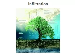
4. What is inflow and infiltration?
5. The context of inflow and infiltration (I/I)Separate sewer systems vs. combined systemsNetwork hydraulicsHydrology (rainfall => runoff, groundwater levels)System operation and management
6. Inflow and infiltration = excess water in the sewer system“Inflow is water that enters the sewer system directly via depressed manhole lids and frames, downspouts, sump pumps, foundation drains, area way drains and cross-connections with storm sewers.” => Fast response to rainfall“Infiltration refers to runoff that infiltrates into the soil before entering a sanitary sewer system through damaged pipe sections, leaky joints or poor manhole connections.” => Slow response to rainfall or continuous/varying infiltration from groundwater Source: Muleta, M.K. and Boulos, P.F., 2008. Analysis and calibration of RDII and design of sewer collection systems. In World Environmental and Water Resources Congress 2008: Ahupua'A (pp. 1-10).
7. Definition for RDII” Rainfall-derived infiltration and inflow (RDII) is the increased portion of water flow in a sanitary sewer system that occurs during and after a rainfall as a source of operating problems in sanitary sewer systems. RDII is the main cause of sanitary sewer overflows (SSO) to basements, streets, or nearby receiving waters.” (EPA 2017)
8. Infiltration, inflowLocal “point sources” of water may cause the majority of the excess flow
9. High wastewater quantities cause problems of various typesOperationalEnvironmentalSocialEconomicHealth
10. Problems more specificallyWhen the system capacity is exceededWastewater is led to nearby rivers, trenches etc. = sewer overflows (CSOs and SSOs)Can also cause uncontrolled consequences such as water flooding on the streets or basementsThe variation in flow volumes causes issues:Larger sized pipes, pumps and treatment plants needed => higher investments needed by reducing I/I it can be possible to e.g. postpone investmentsBut! When the I/I levels are low, the system is oversized
11. Problems more specificallyHigher energy costs needed for pumping in the networkAlso greenhouse gas emissions due to energy consumptionHigher chemical costs at the WWTP + possibly treatment bypassWastewater contains Pathogens => health hazard in e.g. receiving watersNutrients and possibly harmful substances => damage to the environmentImage problemHowever: In oversized systems (relatively typical in Finland), I/I can help maintain the self-rinsing of pipes and thereby prevent blockages
12. Another aspect on I/I: levels indicate network structural conditionHigh I/I levels often imply bad conditionAlso supported by literature Inflow: indicates that stormwater needs to be managed betterInfiltration: indicator for structural condition
13. Sanitary sewer overflows (SSO), combined sewer overflows (CSO)Possible source of inflow!
14. Sewer overflows“Sanitary sewer overflows (SSOs) may occur when the capacity of the collection system is exceeded due to excess wet weather flows, system blockages, or when power and mechanical failures prevent the system from operating properly.”CSO = combined sewer overflow Source: Muleta, M.K. and Boulos, P.F., 2008. Analysis and calibration of RDII and design of sewer collection systems. In World Environmental and Water Resources Congress 2008: Ahupua'A (pp. 1-10).
15. Situation in separate sewers vs. combined sewersSeparateStormwater and sewage conveyed in different systemsSewage to the WWTPStormwater not treated but led to water bodies (rivers, lakes…)90% of systems in FinlandEven separate sewers carry ”excess water” to some extentAnnually e.g. 30% excess flowInstantaneously e.g. 200% flow levels compared to normalCombinedStormwater and sewage in the same system to the WWTPAlso stormwater is treatedBig citiesOld city centersInstantaneously e.g. 10-fold flow levels
16. What are I/I levels likeIn theory, there shouldn’t be any excess flow in the sewer system!In practice, zero levels are never achieved Annual level of 10% I/I of total flow volume is excellent, 40…60% is not unusualThe lower the levels are, the easier the issue is to deal with
17. Separate or combined?
18. QuestionsWhat kind of sewerage do you have in your city or country? Are combined or separate sewers more common, what is the share between those two (do you know)? What are the most common problems regarding sewers that you can hear in the news? What are the I/I levels like in your city or country? Can you tell something about the seasonal variation of those?
19. Detection and reduction of I/I:General principles of I/I reductionLocal source detection
20. I/I can be difficult to tackle, since…The excess flow originates from a wide geographical areaA typical utility has hundreds of kilometers of networkLocal point sources can be a major source of I/IThe system is invisible (underground)Parts of the system are not managed by the utility but by property ownersIn many countries, also in Finland
21. How to reduce I/I”Find out the sources of inflow and infiltration and do something about them”In practice, this often means screening:Get an overview of the situationMove to finer resolution, e.g. network sub-areasFind the specific spots causing the problem
22. Different levels require different measuresGetting an overviewAnnual assessmentHydrodynamic (coarse) modelling of the whole network Getting separate estimates for different network areas Same as above, but with higher resolution data and a possibly higher accuracy model
23. Different levels require different measuresFixing the actual problemsImproving stormwater collection solutionsRenovation and repair ofPipes, manholesHouse lateralsFixing of misconnectionsEither on the utility’s side or the property side
24. Reducing I/I: case HSYMeasures taken / to be taken:Assessment of the flow data quality received from the 500 pumping stations in the networkFound to be often poor, not suitable for I/I analysisConsiderable improvements made to data qualityAlso new measurement points installedImplementation of new district metering areas in the wastewater networkAdjusted radar rainfall data from Finnish Meteorological Institute combined with flow data => estimates on I/I levels HSY = Helsinki Region Environmental Services Authority, provides water and wastewater services in the Helsinki region
25. Local I/I source detection: Smoke tests, visual inspections
26. CCTV inspectionsCan help locate source on I/INot applicable for the whole network at onceOnly useful for detecting infiltrationDetecting inflow requires Good luck with timingAdditional inspections of house laterals
27. Detection and reduction of I/I: Estimation methods and related concepts
28. Methods availableMathematical modelling, statistical methods, machine learning methodsUnit hydrograph analysis (RTK)Hydrodynamic modelling with software such as SWMMSWMM is a physically based, discrete-time simulation model. It employs principles of conservation of mass, energy, and momentum wherever appropriate. More common in purely hydrological modelling and combined sewers SWMM employs the RTK method for RDII calculation.
29. Why model a sewer system?Modelling I/I helps to find sources of I/I Reveals how the system as a whole and its units behave, under different water consumption and weather conditionsFind manholes that flood and pipes that surchargehttps://forums.autodesk.com/t5/civil-3d-forum/ssa-surcharged-inlet-system-losses/td-p/3732598
30. Why model a sewer system?Supports understanding of how the system reacts to different rainfall events in different seasons, times of day etc. Can be used to e.g.Planning measures to prevent sewer overflows Designing new network areas
31. Modelling RDII is “data-derived”The physical processes that result in I/I have very fine resolution and are very complexInstead of trying to model those processes, we analyse the data and conclude the impact of RDIIIn SWMM, RDII is computed independently from the runoff or groundwater flow calculations (!)Basically, it is also possible to construct a sub-catchment for each system node (=manhole) and to direct the runoff into the sewer system
32. Fast vs. slow responseInflow: causes a relatively fast response to rainfall Flow volumes rise soon after the rainfall event startspumping stationsWWTPsInfiltration causes a slower response to rainfall + continuous or seasonally changing (slow / constant) effect on the flows
33. Flow decomposition – flow componentsWet weather flow (WWF) = BWF + RDIIBase Wastewater flow (BWF) = DWF + GWIDry weather flow (DWF) = flow caused by water consumptionGroundwater infiltration (GWI)Rainfall-derived inflow and infiltration RDIIDry weather flowWet weather flowFLOWRAINFALL
34. RDII estimation using a synthetic unit hydrograph, RTK mehtod Source and more information on R, T and K: http://digitalcommons.calpoly.edu/cgi/viewcontent.cgi?article=1275&context=cenv_facUH = unit hydrographTriangles: SHORT/MEDIUM/LONG response
35. The role of data:Data sources and data quality
36. Are our analysis results reliable?The quality of the results highly depends on the quality and quantity of input data (flow measurements, rainfall data, groundwater level…)In an ideal case, there should be data for at least two years to ensure the results are representativeAssumptions made on the following affect the resultsQuantity and variation of water consumption Spatial representativeness of the rainfall estimate (how big is the area where the rainfall is equal)
37. How do we know if the results are reliable?If you assume the water consumption pattern is always the same, the results will be inaccurate but might still be in rangeWays to improve the reliability:Have online water meters installedAt least for large non-residential consumers!If needed, find out about the wastewater production of non-residential consumers – may not always match with water consumptionHave a very short time interval (1 minute)Find similar circumstances (day, time, season) and compare those with and without rain: Métadier, M., & Bertrand-Krajewski, J. L. (2011). Assessing dry weather flow contribution in TSS and COD storm events loads in combined sewer systems. Water Science and Technology, 63(12), 2983-2991. doi: 10.2166/wst.2011.185http://wst.iwaponline.com/content/ppiwawst/63/12/2983.full.pdf
38. Rainfall data – rain gageRain gages:Accurate in estimating local rainfall at the very spot and close to itMust be calibratedLocal conditions such as vicinity to trees or heavy wind may affect the accuracy of the estimatesSpatial variation in rainfall can be considerable; estimate only representative close to the gage
39. Rainfall data - radarRaw rain data from a weather radar:Excellent geographical coverageQuantity estimate can deviate by 100% (e.g. 2mm=>1mm)Adjusted radar data = combines the information from a radar and rain gages => high quality rainfall estimatesIn Finland, often available at a spatial resolution of 1 km2Markus Rantala/Commons/CC-BY-SA-3.0Rule of thumb: A rain gage within a cathment of 1 km2 is more accurate than adjusted radar data, otherwise adjusted radar data is better
40. Sources of flow data Pumping stations send flow dataPermanent source of data; no temporary installations neededQuality may be good, totally useless or anything betweenMagnetic meter reliable, others: check qualityTypically contains missing values, outliers, possibly systematic errors or absolute errors beyond a given valueFlow meters can be installed in the network (manholes)Temporary installationsQuality problems relate typically to the quality of installation (must be calibrated, position must be measured accurately)measurement accuracy, e.g. ±5%
41. Sources of water consumption dataWater meters with automated meter reading (AMR)Send water consumption data e.g. once an hourQuality:Can contain similar issues related to data transfer as pumping station data => Check qualityAlso problems with data transfer and reception, e.g. data from basements may not be well receivedMore often needs to be estimated based on typical water consumption patternsFairly good for estimating water consumption for large residential areasIndustrial consumption must be estimated separately
42. Variation in water consumptionHourly variationTypical peaks around 7-8am and 8-9pm, minimum at 3-4 amSeasonal variationIn Finland, this could be very smallDepends on the area: is there industry where some workers are on vacation in the summer? Is it a place where people come for summer holidays?In many countries pools, watering gardens etc. cause higher water consumption in the summerAnnual variationAre there differences in the number of people living in the area or in the industrial activity between different years?
43. Hourly water consumption of a single propertyTypically two peaks in the day time: one in the morning and one in the evening. The lowest water consumption is late at night / early morning.
44. Hourly water consumption of an area3…5 am7…9 am20…22 am
45. Data resolution matters for I/I estimate resolutionSeveral levels of spatial resolution:The whole network”30 to 40% annually of the total inflow to WWTP”Network subsections”More coming from Northern than Southern parts of the network””Known for main pumping station areas (=sub-catchments) on an annual level”Individual network reaches or pipesLocations of illicit connections or pipes with defects knownTime resolution:Estimated on e.g. on annual levelEstimated on rainfall event level
46. Useful resourcesSWMM user manual: https://nepis.epa.gov/Exe/ZyPDF.cgi?Dockey=P100N3J6.TXTSWMM quick start tutorial: http://ocw.unesco-ihe.org/pluginfile.php/521/mod_resource/content/1/Urban_Drainage_and_Sewerage/8_Modelling_Urban_Drainage/SWMM5/SWMM5%20Quick%20start/SWMM%20QUICK%20START%20TUTORIAL.pdfReview of sewer design criteria and Prediction RDII methods: https://nepis.epa.gov/Adobe/PDF/P1008BP3.pdf
47. Concepts – word of warning
48. Various meanings of ”Inflow”SWMM divides flows to nodes into dry weather inflow (flow in the pipes caused by water consumption)rainfall-derived inflow (runoff that enters the sewer system through manholes)
49. Various meanings of ”Infiltration”Infiltration in hydrological modelling (e.g. SWMM):Infiltration is the rainfall from the pervious area of a subcatchment that infiltrates into the unsaturated upper soil zone and therefore doesn’t form runoff.
50. I/I analysis of the Teekkarikylä catchment
51. Teekkarikylä sewer catchment
52. Data availability for the Teekkarikylä modelA detailed model:All pipes and manholes includedWater consumption data available for many of the propertiesGood quality flow dataPipe locations, lengths, materials, diameters, installation yearsCatchments defined for each manhole, perviousness information availableUnusually good data availabilityBut:No data on groundwater levelsProblems with water consumption data quality
53. Flow dataWater consumptionAvailable for 16 real estates (some 60% in the area) based on automated meter readingEstimated for the rest through interpolation (based on population) + for day care based on literature valuesWastewater flowFlow was measured using an ultrasonic flow meter installed in a manhole at the catchment’s outlet point.
54. Rainfall dataThree different sources:One rain gage about 1km outside the catchment.One rain gage inside the catchmentAdjusted radar data calculated from a 500m x 500m grid