
For correspondence email priyadharsinirssneduin segmentation in detection and morphological R PriyadharsiniT Sree SharmilaDepartment of Computer Science and Engineering and Department of ID: 955672
Download Pdf The PPT/PDF document "CURRENT SCIENCE VOL 115 NO 4 25 AUGUST 2..." is the property of its rightful owner. Permission is granted to download and print the materials on this web site for personal, non-commercial use only, and to display it on your personal computer provided you do not modify the materials and that you retain all copyright notices contained in the materials. By downloading content from our website, you accept the terms of this agreement.


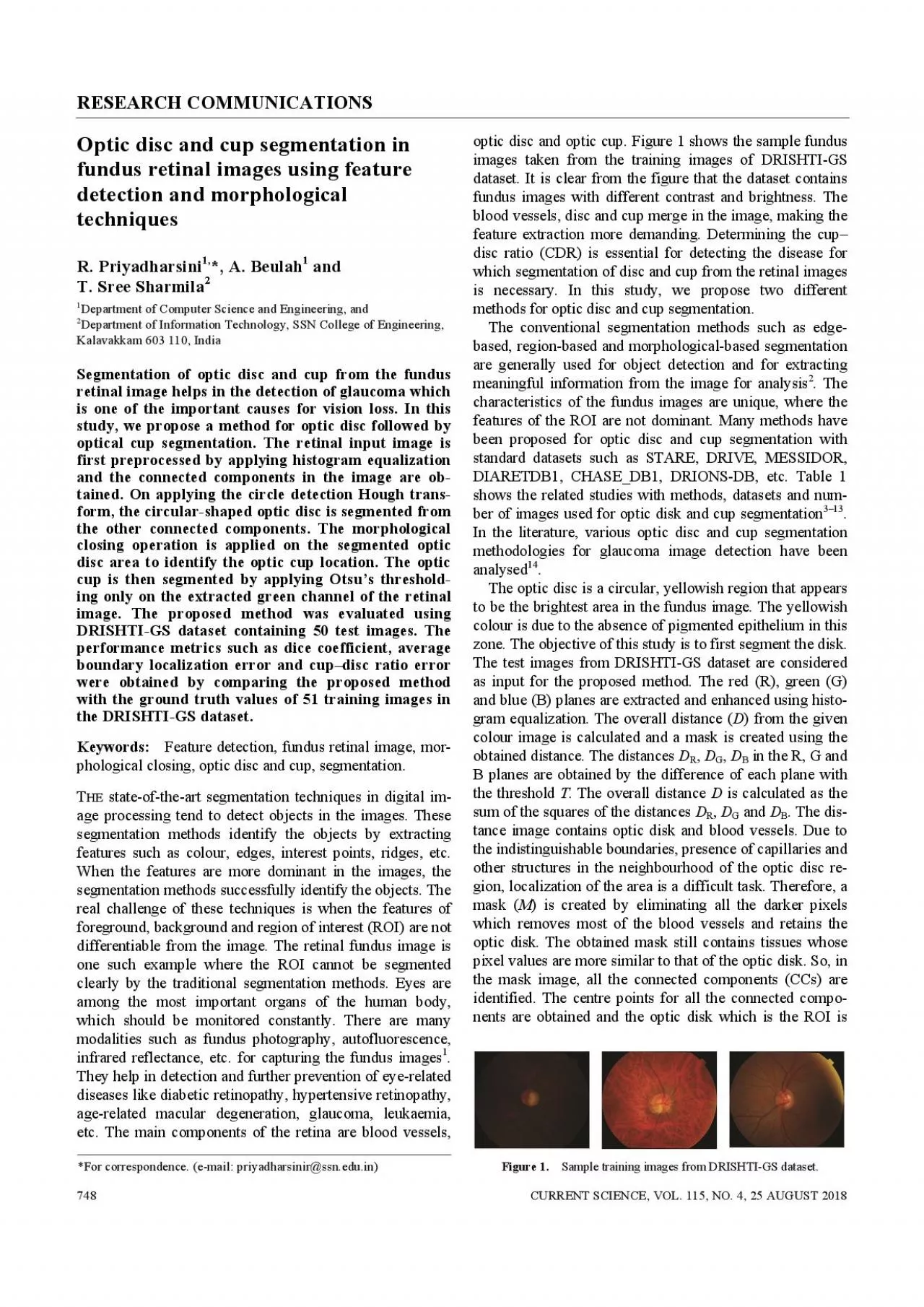
CURRENT SCIENCE, VOL. 115, NO. 4, 25 AUGUST 2018 *For correspondence. (e-mail: priyadharsinir@ssn.edu.in) segmentation in detection and morphological R. PriyadharsiniT. Sree SharmilaDepartment of Computer Science and Engineering, and Department of Information Technology, SSN College of Engineering, Kalavakkam 603 110, India Segmentation of optic disc and cup from the fundus RESEARCH COMMUNICATIONS CURRENT SCIENCE, VOL. 115, NO. 4, 25 AUGUST 2018 Table 1. Literature survey on optic disk and cup segmentation Number of Reference Method used Dataset images used Vessels direction matched filter STARE 81 DRIVE 40 Morphological, edge detection, and feature MESSIDOR 1200 extraction techniques Welfer Adaptive morphological approach DRIVE 40 DIARETDB1 89 Circular Hough transform and grow-cut algorithm DRIVE, DIARETDB1, CHASE_DB1, DRIONS-DB, MESSIDOR and one local Shifa Hospital Database Histogram matching DRIVE, STARE, and a local dataset 273 Ingle and Mishra Gradient method Random images from different source Muramatsu Active contour method, depth map on the basis of stereo Stereo retinal fundus images 80 disparity Combines knowledge-based circular Hough ORIGA 325 transform and a novel optimal channel selection Li and Chutatape Modified active shape model Obtained from clinics by topcon retinal camera 35 Superpixel classification by histograms and centre MESSIDOR 650 surround statistics Tan et al. Multi-scale superpixel classification ORIGA 650 detected by eliminating the unwanted components. As the optic disk in the retina is a circular object, circle detection Hough transform is used for detecting the area. The centre point of the connected components which is close to the centre of the circle detected by the Hough transform is selected as the centre point of the optic disc. The circular object among the connected components is referred to as (CO). Circle Hough transform (CHT) is an efficient technique to detect circles in the image. Shapes can be described in parametric form and a voting scheme is used to f
ind the correct parameters. CHT relies on the equation of circles as follows + (, (1)where b are the coordinates for the centre of the the radius of the circle, and (coordinates. CHT uses the three-dimensional accumulator space for detecting circles with three parameters defined using eq. (2) below. All the edge points in the image are mapped to a set of circles in the accumulator space. The set of circles is defined by all possible values of the radius and centred on the coordinates of the edge point. The radius value remains constant and each edge point defines circles for the other values of the fixed radius. These edge points map to the cone of votes in the accumulator space. Using voting method, circles are detected using the maximum number of votes in the accumulator space which corresponds to the parameters of the circle. The parametric representation of the circle is given by cos(), ). (2) CHT is used for detecting the circular objects in the image. The corresponding connected component selected with the centre point forms the original optic disc. The boundary positions and area of the optic disc are obtained. A bound-ing box (BB) is estimated for the segmented optic disc. The region of interest which is the optic disc is cropped from the original image for further optic cup segmentation. Box 1 shows an algorithm with the steps involved in optic disc segmentation. The optic cup present inside the disc region is not always circular in shape. After segmenting the optic disc, different methods should be followed to segment the optic cup. The shape of the cup varies with the eye and with glaucoma. Morphological closing operation is performed on the image to segment the optic cup. Closing operation smoothens the boundary areas by fusing narrow breaks, eliminates small holes and fills the gaps in the boundary. The closing opera-tion () is defined as I , (3) where represents the input image and is the circular structuring element. Based on the shape of the object to be detected in the image, the structuring element can be defined. The structuring
element probes an image using hit or fit operations. In eq. (3), denotes the morphological dilation and denotes the morphological erosion. Dilation operation is used for thickening the boundaries of the objects of interest in the image, whereas erosion is used to shrink the boundaries. The extent of thickening and thin-ning is a function of shape of the structuring element used. RESEARCH COMMUNICATIONS CURRENT SCIENCE, VOL. 115, NO. 4, 25 AUGUST 2018 Figure 2. , Test images from DRISHTI-GS dataset. , Soft map of optic disc. , Soft map of optic cup. , Segmented optic disc and cup. Table 2. Dataset specification Dataset DRISHTI-GS Images 50 training, 51 testing images Resolution 2896 1944 Ground truth Softmap of optic disc and optic cup for training image respectively. Class 2 is omitted as it has only the back-ground. DICE is defined as 2||DICE.|||| (6) rror (BLE): As DICE does not provide the boundary-level performance analysis, BLE analysis is performed. BLE is the distance (in pixels) between the ground truth and test image boundaries. BLE is defined as BLE||, (7) where is Euclidean distance between the esti-mated boundary in and the centre of the ground truth in , in the direction. is the equi-spaced points. RESEARCH COMMUNICATIONS CURRENT SCIENCE, VOL. 115, NO. 4, 25 AUGUST 2018 Table 3. Performance measure on the DRISTHI-GS test images Optic disc Optic cup DICE BLE DICE BLE 0.85/0.16 27.56/30.55 0.71/0.18 37.08/20.27 Cup-to-disc ratio: This is computed as the ratio of the vertical cup diameter to vertical disc diameter and accurate segmentation of cup and disc is essential for CDR mea-surement. CDR is calculated using the following formula CupareaCDR.Discarea (8) The CDR error is obtained by eq. (9) CDR = |CDR CDR|. (9) Table 3 shows the performance measure on the test images. The absolute CDR error for the test images is 0.27/0.18. All the 51 test images were tested using the proposed optic disc and cup segmentation method. All the test images are of varying brightness and contrast. The optic disc seg-mentation i
s done by first extracting the R, G and B planes and a mask image is created from the overall distance cal-culated. The optic disc is detected from the mask by CHT. All the other connected components are eliminated from the circular objects. The centre point of the connected compo-nents which is close to the centre of the circle detected by the Hough transform is selected as the centre point of the optic disc. The optic cup is segmented by applying the morphological closing operation. The green channel is separated from the morphologically altered image. The Otsus thresholding method is applied on the green channel, which yields the optic cup. The boundary positions and area of the optic cup are obtained. Among the images, 88% of the test images works well for the proposed method. When compared to the ground truth values given in the dataset, absolute CDR error obtained is 0.27. Jain, A. B., Prakash, V. J. and Bhende, M., Techniques of fundus imaging. Med. Vis. Res. Foundations, 2015, (2), 100. Gonzalez, R. C. and Woods, R. E., Image processing. In Digital Image Processing, Prentice Hall, New Jersey, USA, 2007, pp. 104168. Youssif, Aliaa Abdel-Haleim Abdel-Razik, Atef Zaki Ghalwash, and Amr Ahmed Sabry Abdel-Rahman Ghoneim, Optic disc detec-tion from normalized digital fundus images by means of a vessels' direction matched filter. IEEE Trans. Med. Imaging, 2008, (1), 1118. Aquino, A., Gegúndez-Arias, M. E. and Marín, D., Detecting the optic disc boundary in digital fundus images using morphological, edge detection, and feature extraction techniques. IEEE Trans. Med. Imaging, 2010, (11), 18601869. Welfer, D., Scharcanski, J., Kitamura, C. M., Dal Pizzol, M. M., Ludwig, L. W. and Marinho, D. R., Segmentation of the optic disk in color eye fundus images using an adaptive morphological approach. Comput. Biol. Med., 2010, (2), 124137. Abdullah, M., Fraz, M. M. and Barman, S. A., Localization and segmentation of optic disc in retinal images using circular Hough transform and grow-cut algorithm. Peer J, 2016, , e2003. Dehghani, A., Moghaddam, H. A. and Moin, M.
S., Optic disc localization in retinal images using histogram matching. EURASIP J. Image Video Process., 2012, 2012, 11, 19. Ingle, R. and Mishra, P., Cup segmentation by gradient method for the assessment of glaucoma from retinal image. Int. J. Eng. Trends Technol., 2013, (6), 25402543. Muramatsu, C., Nakagawa, T., Sawada, A., Hatanaka, Y., Yama-moto, T. and Fujita, H., Automated determination of cup-to-disc ratio for classification of glaucomatous and normal eyes on stereo retinal fundus images. J. Biomed. Opt., 2011, (9), 096009-1096009-7. 10.Yin, F., Liu, J., Wong, D. W. K., Tan, N. M., Cheung, C., Baska-ran, M. and Wong, T. Y., Automated segmentation of optic disc and optic cup in fundus images for glaucoma diagnosis. In 25th IEEE International Symposium on Computer-based Medical Sys-tems, 2012, pp. 16. 11.Li, H. and Chutatape, O., Boundary detection of optic disk by a modified ASM method. Pattern Recogn., 2003, (9), 20932104. 12.Cheng, J. et al., Superpixel classification based optic disc and optic cup segmentation for glaucoma screening. IEEE Trans. Med. Imaging, 2013, (6), 10191032. 13.Tan, N. M., Xu, Y., Goh, W. B. and Liu, J., Robust multi-scale superpixel classification for optic cup localization. Comput. Med. Imaging Graphics, 2015, , 182193. 14.Almazroa, A. et al., Optic disc and optic cup segmentation metho-dologies for glaucoma image detection: a survey. J. Ophthalmol2015, 180972-1180972-28. 15.Mathworks, I., MATLAB: R2014a. Mathworks Inc, Natick, MA, USA, 2014. 16.Sivaswamy, J., Krishnadas, S. R., Joshi, G. D., Jain, M. and Tabish, A. U. S., DRISHTI-GS: retinal image dataset for optic nerve head (onh) segmentation. In 11th IEEE International Sym-posium on Biomedical Imaging, April 2014, pp. 5356. 17.Dice, L. R., Measures of the amount of ecologic association between species. Ecology, 1945, (3), 297302. 18.Taha, A. A. and Hanbury, A., Metrics for evaluating 3D medical image segmentation: analysis, selection, and tool. BMC Med. Imaging, 2015, (1), 29. Received 9 November 2017; revised accepted 13 May 2018 doi: 10.18520/cs/v115/i4/748