
Conduction problems may involve multiple directions and timedependent conditions Inherently complex Difficult to determine temperature distributions Onedimensional steadystate models can represent accurately numerous engineering systems ID: 557571
Download Presentation The PPT/PDF document "One-Dimensional Steady-State Conduction" is the property of its rightful owner. Permission is granted to download and print the materials on this web site for personal, non-commercial use only, and to display it on your personal computer provided you do not modify the materials and that you retain all copyright notices contained in the materials. By downloading content from our website, you accept the terms of this agreement.


Slide1
One-Dimensional Steady-State Conduction
Conduction problems may involve multiple directions and time-dependent conditions
Inherently complex – Difficult to determine temperature distributions
One-dimensional
steady-state
models can represent accurately numerous engineering systems
In this chapter we will
Learn how to obtain temperature profiles for common geometries with and without heat generation.
Introduce the concept of thermal resistance and thermal circuitsSlide2
Chapter 2 : Introduction to Conduction
2
For
cartesian
coordinates
(2.17)Slide3
Chapter 3 : One-dimensional, Steady state conduction (without thermal generation)
3
3.1 Methodology of a conduction analysis
Specify appropriate form of the heat equation
Solve for the temperature distribution
Apply Fourier’s law to determine the heat flux
Simplest case:
- One-dimensional, steady state conduction with no thermal energy generation
Common geometries:
The plane wall: described in rectangular (x) coordinate. Area perpendicular to direction of heat transfer is constant (independent of x).
Cylindrical wall : radial conduction through tube wall
Spherical wall : radial conduction through shell wallSlide4
Chapter 3 : One-dimensional, Steady state conduction (without thermal generation)
4
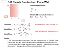
3.2 The plane wall – temperature distribution
assuming
steady-state
conditions and no
internal heat generation (i.e.
q = 0), then the 1-D heat conduction equation reduces to:
For
constant
k
and
A,
second order differential equation:
.
This mean:Heat flux (
q”x) is independent of x
Heat rate (qx) is independent of x
Boundary conditions:
T(0)
=
T
s,1
T(L)
=
T
s,2
Using Eq. (2.2) in Chapter 2, bySlide5
Chapter 3 : One-dimensional, Steady state conduction (without thermal generation)
5
1-D heat conduction equation for
steady-state
conditions and no
internal heat generation
(i.e. q
= 0), is.
for
constant
k
and
A
Integrate twice to get
T(x)
For boundary conditions:
T(0)
= T
s,1
and
T(L)
=
T
s,2
at x = 0, T(x) =
T
s,1
and
C
2
=
T
s,1
at x = L, T(x) =
T
s,2
and
T
s,2
=
C1 L + C2 = C1 L + Ts,1
this gives, C1 = (Ts,2 – Ts,1)/2
and
Using value of
C1 and C2, the function of T(x) is
*From here, apply Fourier’s law to get heat transfer,
q
xSlide6
Chapter 3 : One-dimensional, Steady state conduction (without thermal generation)
6
Heat rate for plane wall (simplest case):
Heat flux for plane wall (simplest case):Slide7
Chapter 3 : One-dimensional, Steady state conduction (without thermal generation)
7
Example: Temp distribution problem
Consider a large plane wall of thickness L = 0.2 m, thermal conductivity k = 1.2 W/
mK
, and surface area, A = 15m2. The two sides of the wall are maintained at constant temperatures of T1
= 120C and T2 = 50C. Determine,
The temperature distribution equation within the wallValue of temperature at thickness of 0.1mThe rate of heat conduction through the wall under steady conditionsSlide8
Thermal Resistance
Based on the previous solution, the conduction heat transfer rate can be calculated:
Recall electric circuit theory - Ohm’s law for electrical resistance:
Similarly for heat convection, Newton’s law of cooling applies:
And for radiation heat transfer:
(3.2a)
(3.2b)
(3.2c)
.
.
.Slide9
Thermal Resistance
Compare with equations 3.2a-3.2c
The temperature difference is the “potential” or
driving force
for the heat flow and the combinations of thermal conductivity, convection coefficient, thickness and area of material act as a
resistance
to this flow:
We can use this electrical analogy to represent heat transfer problems using the concept of a thermal circuit (equivalent to an electrical circuit).
.Slide10
Chapter 3 : One-dimensional, Steady state conduction (without thermal generation)
10
3.2.1 Thermal resistances & Thermal circuits
Interestingly, there exists an analogy between the diffusion of heat and electrical charge. For example if an electrical resistance is associated with the conduction of electricity, a thermal resistance may be associated with the conduction of heat.
Defining thermal resistance for conduction in a plane wall:
For convection :
For previous simplest case, thermal circuit for plane wall with adjoining fluids:Slide11
Chapter 3 : One-dimensional, Steady state conduction (without thermal generation)
11
3.2.1 Thermal resistances & Thermal circuits
In case of radiation :
where,
Surface temperature
Surrounding temperature
(3.13)
(1.9)Slide12
Chapter 3 : One-dimensional, Steady state conduction (without thermal generation)
12
Example: (Problem 3.2a)
The rear window of an automobile is defogged by passing warm air over its inner surface. If the warm air is at
T
,i
= 40C and the corresponding convection coefficient is hi = 30 W/m2
K, what are the inner and outer surface temperatures of 4-mm thick window glass, if the outside ambient air temperature is T,o = -10C and the associated convection coefficient is
h
o
= 65 W/m
2
K.Slide13
Chapter 3 : One-dimensional, Steady state conduction (without thermal generation)
13
Example (problem 3.5):
The walls of a refrigerator are typically constructed by sandwiching a layer of insulation between sheet metal panels. Consider a wall made from fibreglass insulation of thermal conductivity,
k
i = 0.046 W/mK
and thickness Li = 50 mm and steel panels, each of thermal conductivity kp
= 60 W/mK and thickness Lp = 3 mm. If the wall separates refrigerated air at
T
,o
= 25C, what is the heat gain per unit surface area ?
Coefficients associated with natural convection at the inner and outer surfaces can be approximated as
h
i = ho = 5 W/m2KSlide14
Chapter 3 : One-dimensional, Steady state conduction (without thermal generation)
14
3.2.2 The composite wall (with negligible contact resistance)Slide15
Chapter 3 : One-dimensional, Steady state conduction (without thermal generation)
15
Composite wall with negligible contact resistance:
where,
Overall heat transfer coefficient:
* A modified form of Newton’s Law of cooling to encompass multiple resistances to heat transfer
The composite wall (series type)Slide16
Composite Walls
What is the heat transfer rate for this system?
Alternatively
where U is the
overall heat transfer coefficient
and
D
T the overall temperature difference.
.Slide17
Chapter 3 : One-dimensional, Steady state conduction (without thermal generation)
17
The composite wall (parallel type)Slide18
Chapter 3 : One-dimensional, Steady state conduction (without thermal generation)
18
The composite wall (parallel type)
Electric analogy of thermal circuits
- To solve a parallel resistance network like that shown opposite, we can reduce the network to and equivalent resistance
For electrical circuits:
For thermal circuits:Slide19
Chapter 3 : One-dimensional, Steady state conduction (without thermal generation)
19
Example: parallel resistances
*IR (infrared) photos show that the heat transfer through the built-up walls is more complex than predicted by a simple parallel-resistance.Slide20
Chapter 3 : One-dimensional, Steady state conduction (without thermal generation)
20
Example: (3.15)
Consider a composite wall that includes an 8-mm thick hardwood siding, 40 mm by 130 mm hardwood studs on 0.65 m
centers
with glass fibre insulation (paper faced, 28 kg/m3) and a 12 mm layer of gypsum wall board.
What is the thermal resistance associated with a wall that is 2.5 m high by 6.5 m wide (having 10 studs, each 2.5 m high)Slide21
Chapter 3 : One-dimensional, Steady state conduction (without thermal generation)
21
Example of resistance network with both
radiative
and
convective boundary (Example 3.1)Slide22
Contact ResistanceSlide23
Chapter 3 : One-dimensional, Steady state conduction (without thermal generation)
23
3.3 Contact resistance
It is important to
recognise
that, in composite systems, the temperature drop across the interface between material may be appreciable (present analysis is neglected).
This attributed is due to thermal contact resistance
Rt,c
*values depend on: materials A and B, surface finishes, interstitial conditions and contact pressureSlide24
Composite Walls – with contact resistancesSlide25
Chapter 3 : One-dimensional, Steady state conduction (without thermal generation)
25Slide26
Chapter 3 : One-dimensional, Steady state conduction (without thermal generation)
26Slide27
Chapter 3 : One-dimensional, Steady state conduction (without thermal generation)
27
3.3 Radial systems: cylindrical wall
General heat equation for cylinder (from Chap. 2)
For 1-D steady state, with no heat generation
Integrate twice to get temperature distribution,
T(r).
For example, for constant temperature boundary:
From
T(r)
, heat flux for cylinderSlide28
Chapter 3 : One-dimensional, Steady state conduction (without thermal generation)
28
The thermal resistance for radial conduction
In case of cylinder with composite wall (negligible contact resistance)Slide29
Chapter 3 : One-dimensional, Steady state conduction (without thermal generation)
29
Critical radius for insulation
Adding more insulation to a
wall
decrease heat transfer
The thicker the insulation, the lower the heat transfer through the wall
However, adding insulation to a
cylindrical pipe
or a
spherical shell
is a different matter.
Additional insulation increase the conduction resistance of the insulation layer but decrease the convection resistance of the surface because of the increase in the outer surface area for convection
Hence, knowledge of critical radius of insulation is required Slide30
Chapter 3 : One-dimensional, Steady state conduction (without thermal generation)
30
Critical radius for insulation: see example 3.5 in Textbook for details
If
r
i
<
r
cr
,
R
tot
decreases and the heat rate therefore increases with insulation
If
r
i >
rcr, R
tot increases and therefore heat rate decreases with insulation
Insulation prop.
Outside conv.
coeff
.Slide31
Chapter 3 : One-dimensional, Steady state conduction (without thermal generation)
31
Example 3.39: cylinder
A stainless steel (AISI 304) tube used to transport a chilled pharmaceutical has an inner diameter of 36 mm and a wall thickness of 2 mm. The pharmaceutical and ambient air are at temperatures of 6
C and 23C, respectively, while the corresponding inner and outer convection coefficients are 400 W/m
2
K and 6 W/m2K, respectively.What is the heat gain per unit tube length (W/m) ?
What is the heat gain per unit length if a 10-mm thick layer of calcium silicate insulation (kins
= 0.050 W/
mK
) is applied to the tube. Discuss the result with the knowledge of
r
crit
.
(12.6 W/m, 7.7 W/m)Slide32
Chapter 3 : One-dimensional, Steady state conduction (without thermal generation)
32
3.4 Radial systems: spherical wall
General heat equation for sphere (from Chap. 2)
For 1-D steady state, with no heat generation
Integrate twice to get temperature distribution for constant
k
,
T(r)
From
T(r)
, heat flux for sphereSlide33
Chapter 3 : One-dimensional, Steady state conduction (without thermal generation)
33
The thermal resistance for radial conduction in sphere
In case of sphere with composite shell (negligible contact resistance)
The total thermal resistance due to conduction and convection in sphereSlide34
Chapter 3 : One-dimensional, Steady state conduction (without thermal generation)
34
SummarySlide35
Chapter 3 : One-dimensional, Steady state conduction (without thermal generation)
35
Example 3.54:
A storage tank consists of a cylindrical section that has a length and inner diameter of L=2m and D
i
=1m, respectively, and two hemispherical end sections. The tank is constructed from 20 mm thick glass (Pyrex) and is exposed to ambient air for which the temperature is 300K and the convection coefficient is 10 W/m
2K. The tank is used to store heated oil, which maintains the inner surface at a temperature of 400K. Determine the electrical power that must be supplied to a heater submerged in the oil if the prescribed conditions are to be maintained. Radiation effects may be neglected, and the Pyrex may be assumed to have a thermal conductivity of 1.4 W/mK.