

Julia Bobak Nanofab Workshop February 11 2014 Outline Turbo and turbomolecular pumps Vacuum pump comparisons History Design Operational considerations Applications A quick definition to start ID: 512353
Download Presentation The PPT/PDF document "Turbo Pumps" is the property of its rightful owner. Permission is granted to download and print the materials on this web site for personal, non-commercial use only, and to display it on your personal computer provided you do not modify the materials and that you retain all copyright notices contained in the materials. By downloading content from our website, you accept the terms of this agreement.


Slide1
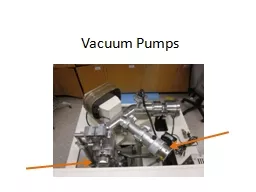
Turbo Pumps
Julia
Bobak
Nanofab
Workshop
February 11, 2014Slide2
OutlineTurbo and turbomolecular pumpsVacuum pump comparisonsHistory
Design
Operational considerations
ApplicationsSlide3
A quick definition to startTurbo vs. turbomolecular pumpsTurbomolecular pump: high vacuum pump
Turbo pump: propellant pump
The space shuttle’s main turbo
pump delivers
150 lb of liquid hydrogen and 896 lb of liquid oxygen to the engine per second.Slide4
Pump comparisonTo achieve ultra high vacuum, we usually rely on a series of three pumps:Rotary pump ( ~ 10-4
Torr)Invented by Charles C. Barnes of New Brunswick
!
Turbopump
(~ 10
-3
– 10
-7
Torr)Ion pump (~ 10-6 – 10-11 Torr)Slide5
HistoryFirst developed and patented at Pfeiffer Vacuum by Dr. W. Becker. Became commercially available in 1957.
Before that, there were molecular drag pumps, which had a tendency to mechanical seizure.Slide6
Design
Bearings: can be oil lubricated or, more often now, magnetically levitated.Slide7
OperationThe rotor blades spin around at up to 90,000 rpmWhen then hit gas molecules in the chamber they impart momentumThe angles of the rotor and stator blades drives the gas molecules towards the exhaust
Rotor
Stator
Outlet
Inlet
Net gas flowSlide8
Operating criteriaAt atmospheric pressure, the behaviour of gases is described as “
viscous flow”.The gas molecules move in bulk and interact more with each other than with the walls of the container.
Most
turbopumps
will not work in this case because the momentum imparted by the rotors is insignificant compared with intermolecular interactions.
A
roughing pump
is used to get the pressure down to ~10
-3 Torr In this regime, gas molecules behave approximately independently. This is described as “molecular flow”.Now the turbopump can impart momentum on each molecule individually.Slide9
Limiting factorsA turbopump alone is insufficient to achieve ultra high vacuumAt a certain point the pressure will cease dropping due to…
1. Desorption of materials from seals and bearings, which increases at lower pressures.2. Leaks through the seals, which are also enhanced at low pressure.
3. Reaching maximum compression ratio.
K =
P
outlet
/
P
intakeKmax = {exp[(vBM
1/2
)/(2k
B
NAT)1/2]f(Φ)}n
vB = velocity of the bladesM = molar mass of the gasT = temperaturef(Φ) = function of blade anglen = number of bladesSlide10
Pumping speed vs. pressureDifferent gases pump down at different ratesCompression ratio varies exponentially with molecular weight of gasesSlide11
Applications
Focused ion beam system
Scanning electron microscope
Space simulators
Thin film deposition
SynchrotronsSlide12
Questions
References:
T.A
.
Delchar
.
Vacuum
Physics and
Techniques, (Chapman & Hall, 1993).
Pfeiffer
Vaccum
.
Working with Turbopumps: Introduction to high and ultra high vacuum production. http://www.pfeiffer-
vacuum.com.Weissler, G.L. & Carlson, W.R., eds. Vacuum Physics and Technology, (Academic Press, 1908).