
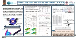
Iron master Load key Bladder location Assembly alignment slots LHe SS vessel Cooling hole Titanium pole Coil Welding strip slot Alignment key location Al bolted collar 4563 mm 4963 mm Mechanical Design Studies of the MQXF Long Model Quadrupole for the ID: 779846
Download The PPT/PDF document "Al shell Iron yoke Iron pad" is the property of its rightful owner. Permission is granted to download and print the materials on this web site for personal, non-commercial use only, and to display it on your personal computer provided you do not modify the materials and that you retain all copyright notices contained in the materials. By downloading content from our website, you accept the terms of this agreement.


Slide1
Al shell
Iron yoke
Iron pad
Iron master
Load key
Bladder location
Assembly alignment slots
LHe
SS vessel
Cooling hole
Titanium pole
Coil
Welding strip slot
Alignment key location
Al bolted collar
4563 mm
4963 mm
Mechanical Design Studies of the MQXF Long Model Quadrupole for the
HiLumi
LHC
H. Pan, E.
Anderssen
, G.
Ambrosio
, D. W. Cheng, M.
Juchno
, P.
Ferracin
, H. Felice, J. C. Perez, S. O.
Prestemon
, G.
Vallone
4LPo1J-07
ABSTRACT
The Large Hadron Collider Luminosity upgrade (
HiLumi
) program requires new low-β triplet quadrupole magnets, called MQXF, in the Interaction Region (IR) to increase the LHC peak and integrated luminosity. The MQXF magnets, designed and fabricated in collaboration between CERN and U.S. LARP, will all have the same cross section. The MQXF long model, referred as MQXFA, is a quadrupole using the Nb3Sn superconducting technology with 150 mm aperture and a 4.2 m magnetic length and is the first long prototype of the final MQXF design. The MQXFA magnet is based on the previous LARP HQ and MQXFS designs. In this paper we present the baseline design of the MQXFA structure with detailed 3D numerical analysis. A detailed tolerance analysis of the baseline case has been performed by using a 3D finite element model, which allows fast computation of structures modelled with actual tolerances. Tolerance sensitivity of each component is discussed to verify the actual tolerances could be achieved by vendors. Tolerance stack-up analysis is presented in the end of this paper.
INTRODUCTION
3D Numerical Model
Mechanical Tolerance Analysis
Tolerance analysis in this study is based on the linear dimensional chain calculation.
Each of the parts that stacked on top of the coils will affect the coil stress, and all of the tolerances associated on those parts need to managed.
The baseline case chooses 850
μ
m interference as the target net shim thickness.
The shell azimuthal stress is 120 MPa after pre-loading;. and 55% of force from shell is transferred to the coils;
Shell stress becomes 208 MPa after cool-down to transfer 66% of the shell force.
Peak coil stress of 192 MPa occurs after cool-down, and within the safe stress level.
Conclusion
The
baseline interference meet the maximum gradient operation is set 850 μm.
The
mechanical impact of stainless steel with pretension
of 100 MPa is checked.
The mechanical tolerances
of each individual part affect the coil stress slightly. Pad and pad master are the most sensitive parts among the structure components.
The
maximum coil stress deviation is ± 32 MPa at cold in the
Worst Case (WC);
however, based on the manufacturing experiences, the coil stress deviation could be lowered to ±9 MPa with RSS method
Fully
parametric FE model of MQXFA was developed in ANSYS on basis of the previous MQXFS
model:
RT, preloading
1.9 K
130 T/m
140 T/m
140 T/m
130 T/m
Key
SS
LHe
Vessel
1.9 K
Fully
parametric FE model of MQXFA was developed in ANSYS on basis of the previous MQXFS
model:
Elements
were generated using a volume sweep of 20-node structural element (SOLID186).
The
contact areas between the assembly components were modeled with TARGE170 and CONTA174 elements with asymmetric behavior and augmented Lagrange formulation. Friction coefficient of 0.2 was used at the interfaces of support components.
Worst case method,
also
known as linear
stack-up:
Statistical tolerancing, also refers to RSS (Root Sum Squares):