
CENTURION UNIVERSITY CONTENTS INTRODUCTION HISTORY PARTS OF CT SCAN MACHINE PRINCIPLE OF CT SCAN Basics of CT scan The term Computed Tomography Tomo slices section to cut ID: 1041898
Download Presentation The PPT/PDF document "COMPUTED TOMOGRAPHY AASIF LONE" is the property of its rightful owner. Permission is granted to download and print the materials on this web site for personal, non-commercial use only, and to display it on your personal computer provided you do not modify the materials and that you retain all copyright notices contained in the materials. By downloading content from our website, you accept the terms of this agreement.


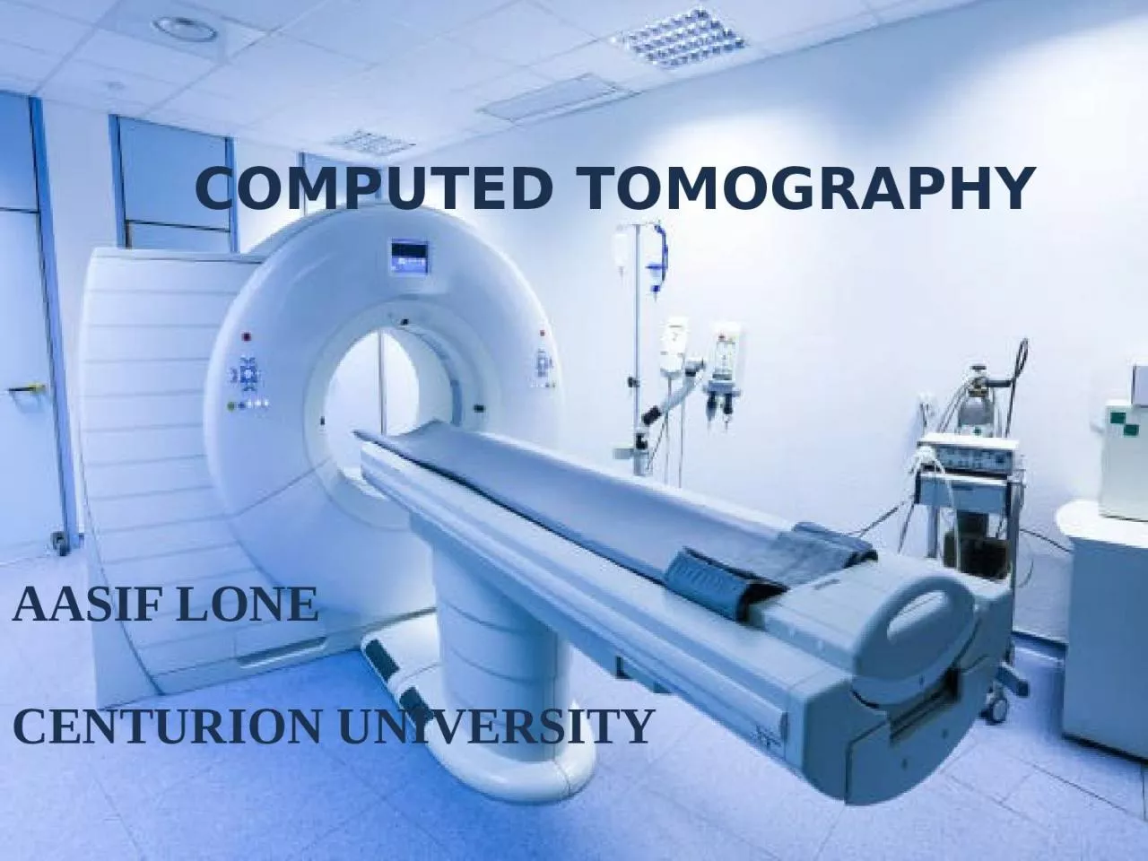
1. COMPUTED TOMOGRAPHYAASIF LONECENTURION UNIVERSITY
2. CONTENTSINTRODUCTION HISTORY PARTS OF CT SCAN MACHINE PRINCIPLE OF CT SCAN Basics of CT scan
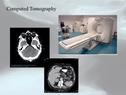
3. The term ‘Computed Tomography’ Tomo- slices, section, to cut graphy- to write, draw, picture It is a medical imaging technique that uses computer processed combinations of multiple x-ray measurements taken from different angles of body.INTRODUCTION
4. HISTORY OF CT SCANIn 1917, Johann Radon, an Australian mathematician presented an algorithm for creating an image from a set of measured projection data. First CT machine used for clinical purpose was developed by late Sir Godfrey Hounsfield, was installed at Atkinson Morley Hospital, London in early 1970s. Over the decades the CT machines became faster as the processing power of computers improved.HISTORY OF CT SCAN
5. In late 1980s , the development of slip ring technology enables continuous revolution of X-ray unit , which not only reduce the acquisition time per axial image to 1s but also allowed helical data to be acquired. This revolutionized CT , because the whole organ systems could be now examined continuously during a single breath hold. The next step of development occurred in late 1990s, when detectors were split into multiple thin rows along z axis to permit acquisition of multiple sections simultaneously, MULTIDETECTOR CT. this decreased acquisition time further and made it possible to use thin sections.
6. Gantry X-Ray Tubes X-Ray Detectors Filter CollimatorPARTS OF CT SCAN MACHINE
7. GANTRY It is the major component of CT system It’s a movable frame that contains x ray tube, filter, detector. Revolve around the patient. Acquire information at different angles and projections. Slipring technology eliminated the need of cables and allow continuous rotation of gantry components. The opening through which patient passes is called gantry aperature. Diameter ranges from 50 to 85cms
8.
9. XRAY TUBE 3 main parts of X-ray tube anode, cathode, filament. When filament is heated , electrons are ejected from its surface and move towards anode
10.
11. COLLIMATOR It’s the important component for reducing radiation dose and improving image quality by reducing scatter radiation Narrowing and widening of beamreduces the overall integral dose to the patient and thus minimizes the radiation risk. Less volume irradiated will result in less x-ray scatter incident on the detector. This results in improved subject contrast and image quality.
12.
13. FILTER Made of aluminium or Teflon Provide equal photon distribution across the X-ray beam. Reduce overall patient dose by removing softer radiation
14. DETECTORS They gather information by measuring the X-ray attenuation through objects Detectors collect information regarding the degree to which each anatomic structure attenuated the beam during a CT Scan Machine .Instead of film to record the attenuated beam , digital x-ray detectors collect the information in CT Scans
15. The X-ray pass through body and are detected by a detector positioned on opposite side of body. The projection data must be acquired from multiple angle around the body. From these data the computer reconstructs an imagePRINCIPLE OF CT SCAN
16. CT uses a combination of X-rays and computer technology to produce images of the inside of the body. It shows detailed images of any part of the body, including the bones, muscles, fat, organs and blood vessels.
17. CT uses ionizing radiation, or x-rays, coupled with an electronic detector array to record a pattern of densities and create an image of a “slice” or “cut” of tissue. The x-ray beam rotates around the object within the scanner such that multiple x-ray projections pass through the object.
18.
19. SLICE MATRIX PIXEL VOXEL CT NUMBER WINDOWING WINDOW WIDTH WINDOW LEVEL PITCHVARIOUS PARAMETERS OF CT
20. The cross section portion of body which is scanned for production of CT image is called Slice. The slice has width and therefore volume.The width is determined by width of the x rays beam.SLICE/CUT
21. Think like looking into the loaf of bread by cutting into the thin slices and then viewing the slice individually.Cross Sectional Slices
22. The CT image is represented as the Matrix of the number. A two dimensional array of numbers arranged in rows and columns is called Matrix. Each number represent the value of the image at that location.MATRIX
23. Each square in a matrix is called a pixel. Also known as picture element.PIXEL
24. Each individual element or number in the image matrix represents a three dimensional volume element in object called VOXEL. Since a CT section has a finite thickness, each pixel actually represents a small volume element, or voxel. The size of this voxel depends on the matrix size, the selected field of view (FOV), and the section thicknessVOXEL
25. CT image is composed of thousands of tiny squares (pixels) each of which computer assigned , a CT number from -1000 to +1000, measured in Hounsfield unit, named after sir Godfrey Hounsfield. CT number vary according to the density of tissue. It is the measure of how much X-ray beam is absorbed. Dense substance absorbs more Xray, high CT number, increased attenuation, displayed as whiter densities (Hyperdense) Less dense substance absorbs few Xray, has low CT number, decreased attenuation. Are Displayed as black densities (Hypodense)CT NUMBER
26. Related to different composition and nature of Tissue. X-ray attenuation depends on both the density and atomic number(z) of materials and the energy of the x-ray photons. For CT imagining a high KV(like 120- 140) and heavy beam filtration is used. This minimizes the photoelectric interactions that are influenced by the material. Therefore, CT number are determined by the density of the tissues or materials.HOUNSFIELD UNITS(HU)
27. Air-1000Fat-100Pure water0CSF15White Matter45Gray Matter40Blood20Bone/Calcification+1000TISSUE & CT NUMBER
28. The relationship between patient and tube motion is called Pitch. It is defined as table movement during each revolution of x-ray tube divided by collimation width. For example: For a 5mm section, if patient moves 10mm during the time it takes for the x-ray tube to rotate through 360˚, the pitch is 2. Increasing pitch reduces the scan time and patient dosePitch
29. Spatial resolution- ability to differentiate small objects that are adjacent to one anotherContrast resolution- ability of CT scan to differentiate small attenuation .Image noise- one of the limiting factor of CT image quality. It’s a portion of signal that contains no information. It is characterized by grainy appearance of image Image artefact- any distortion or error in the image that is unrelated to subject. Motion, metallic objects, equipment malfunction may cause artifacts.CT IMAGE QUALITY
30.