
section for the DESO stem Do not Discard theretainer spring or valve stem2 Remove the DESO Oring from the valve stem with a small pick and discardQC Series QuickConnectsaaintenance Instrucx00740069o ID: 869853
Download Pdf The PPT/PDF document "1 Follow steps 1 through 6 of the Disass..." is the property of its rightful owner. Permission is granted to download and print the materials on this web site for personal, non-commercial use only, and to display it on your personal computer provided you do not modify the materials and that you retain all copyright notices contained in the materials. By downloading content from our website, you accept the terms of this agreement.


1 1. Follow steps 1 through 6 of the Disas
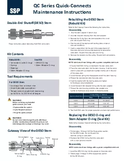
1. Follow steps 1 through 6 of the Disassembly section for the DESO stem. Do not Discard the retainer, spring or valve stem. 2. Remove the DESO O-ring from the valve stem with a small pick and discard. QC Series Quick-Connects aaintenance Instruc�ons WARNING Before servicing any installed quick-connect, you must: WARNING of other manufactures. Rebuild kit parts are not interchangeable. Leakage or blockage may occur. • Valve stem (with O-ring) • Spring • Retainer • Stem Adapter O-ring • Locking pliers or bench vise Torque wrench capable of measuring up to 20 in.·lb (2.3 N·m) of torque • DESO O-ring • Stem Adapter O-ring Double-End Shuto� (DESh) Stem webuilding the DESh Stem (webuild Kit) weassembly weassembly Kit Contents webuild Kit For DESh Stem These instructions detail rebuilding the DESO valve stem. • Depressurize the system • Cycle the quick-connect • Purge the quick-connect Cutaway View of the DESh Stem Retainer Spring Valve Stem Stem Housing DESO O-ring Stem Adapter Stem Adapter O-ring Slot Refer to the Cutaway View while following the instructions. 1. Grip the stem adapter in bench vise. 2. Unscrew the stem housing from the stem adapter. 3. Remove the O-ring from the stem adapter with a small pick and discard the O-ring. 4. Grip the end of the retainer with locking pliers or bench vise and hold �rmly. 5. Insert a screwdriver into the slot in the opposite end of the valve stem and turn counterclockwise to remove the valve stem. Discard the valve stem and O-ring. 6. Remove the retainer and the spring. Discard both components. 1. Ensure the DESO O-ring is installed on the new valve stem. 2. Place the new valve stem into the stem housing. Hold the valve stem in place with a screwdriver inserted into the slot in the end of the valve stem. 3. Install the new spring into the opposite end of the stem housing. 4. 5. Hold the retainer with the locking pliers and tighten to the torque valve listed below. 6. Install the new Stem Adapter O-ring onto the stem adapter. 7. tighten to the torque value shown in the tables below. 1. Install the DESO O-ring into the groove on the valve stem. 2. for the DESO stem. NOTE: Lubricate all new O-rings with a system compatible Lubri
2 cant. NOTE: Lubricate all new O-rings wi
cant. NOTE: Lubricate all new O-rings with a system compatible Lubricant. Test the DESO stem for proper operation and leak-tight performance. Quick-Connect Size Torque Value, in.·lb (N·m) Brass Stainless Steel 1/4 in. 0.5 (0.06) 1.1 (0.12) 3/8 in. 4.25 (0.48) 13 (1.47) 1/2 in. 7.0 (0.79) 13 (1.47) weplacing the DESh h-ring and Stem Adapter h-ring (Seal Kit) Refer to the Cutaway View while following the instructions. Install the new Body Adapter O-ring onto the body adapter. 2. Install the new Stem Seal O-ring into the body housing. 4. Install the new Insert O-ring, pressing radially to ensure proper installation of O-ring. 5. Place the new body valve into the body housing. 6. Place the new valve spring into the body valve. to the torque value shown in the tables below. 1. Grip the body adapter in bench vise. Unscrew the housing from the body adapter. 3. Remove the valve spring and body valve. a small pick and discard. 5. Remove the insert and Stem O-ring with a small pick and discard. Remove the Body Adapter O-ring from the body adapter with a small pick and discard. Body Adapter O-Ring Insert O-ring www.mySSt.com QC Series Quick-Connects These instructions detail rebuilding the QC Series body. WARNING Before servicing any installed quick-connect, you must: • Stem O-ring • Insert O-ring • Body Adapter O-ring • Body Valve (with O-ring) • Valve Spring • Wrench • Bench vise Torque wrench capable of measuring up to 400 in.·lb (45.2 N·m) of torque Kit Contents Tool wequirements • Depressurize the system • Cycle the quick-connect • Purge the quick-connect Cutaway View of the .ody Housing Body Valve Wrench Loca�on Do not apply a wrench to this loca�on. Body Adapter Valve O-ring Stem O-ring Insert Valve Spring webuilding the .ody weassembly Refer to the Cutaway View while following the instructions. Test the body for proper operation and leak-tight performance. Quick-Connect Size Torque Value, in.·lb (N·m) Brass Stainless Steel 1/4 in. 150 ± 10 (16.9 ± 1.1) 3/8 in. 1/2 in. WARNING Do not mix or interchange kit parts with those of other manufactures. Rebuild kit parts are not interchangeable. Leakage or blockage may occur. NOTE: Lubricate all new O-rings with a system compatible Lubricant