
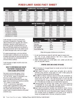
11455mm to 16335mm 16535mm to 22885mm 22885mm to 31140mm FIXED LIMIT GAGE FACT SHEETFixed limit gages are primarily used to check dimensions and geometries Plug gages check internal dimensions and ID: 873618
Download Pdf The PPT/PDF document "GAGEMAKER146S TOLERANCE CHART XXXX XXX..." is the property of its rightful owner. Permission is granted to download and print the materials on this web site for personal, non-commercial use only, and to display it on your personal computer provided you do not modify the materials and that you retain all copyright notices contained in the materials. By downloading content from our website, you accept the terms of this agreement.


![NHS | Presentation to [XXXX Company] | [Type Date]](https://thumbs.docslides.com/398711/nhs-presentation-to-xxxx-company-type-date.jpg)


1 GAGEMAKER’S TOLERANCE CHART XXXX
GAGEMAKER’S TOLERANCE CHART XXXX XXX XX X Y Z ZZ.0009” to.8250”.8251” to 1.5100”1.5101” to 2.5101”2.5101” to 4.5100”4.5101” to 6.5100”6.5101” to 9.0100”9.0101” to 12.260” 114.55mm to 163.35mm 165.35mm to 228.85mm 228.85mm to 311.40mm FIXED LIMIT GAGE FACT SHEETFixed limit gages are primarily used to check dimensions and geometries. Plug gages check internal dimensions and ring gages check external dimensions. Inspection is performed by use of GO/NOGO gages that represent the Minimum and Maximum limit of the product part characteristic to ensure assembleability and fit. This method is used for both thread gages and cylindrical plain gages. GO gages passing through a part assure that the maximum material condition of a part has not been exceeded. NOGO gages not passing through the part assure the dimension has not dropped below the minimum material condition.Fixed limit gages are highly accurate, easy to use, and economical.HOW TO DETERMINE AND SELECT THE PROPER TOLERANCE FOR YOUR GAGING APPLICATIONThe normal rule of practice requires 10% of TOLERANCE DIRECTION Type of Gage GO Member NOGO Member Thread plug Minus Plain plug Minus Thread ring gage Plus Plain ring gage Plus Thread Setting Plug PlusWhen ordering gages, the two basic principles are:Do not allow the tolerance of the GO and NOGO gages to consume more than 10% of your product tolerance. The 10% is usually divided equally between the GO and NOGO gages.Higher precision gages will accept slightly more product but with less wear life and greater expense.PROPER CARE AND USAGE OF GAGESPart dimensions to be gaged should be cleaned and burr free to prevent gaging interference.Gages should be turned or pushed slowly and gently into or onto the dimension being checked. Forcing gages will result in faulty gaging and the possibility of damaging both the part and gage. TCI_Catalog_1008.indd 28 10/21/08 7:51:00 PM