
of14LOCB2011TycoElectronicsCorporationaTEConnectivityLtdCompanyAllRightsReservedTrademarkTEConnectivityTEconnectivitylogoandTElogoaretrademarksOtherlogosproductandorCompanynamesmaybetradem ID: 298199
Download Pdf The PPT/PDF document "ApplicationSpecificationPre-InsulatedDia..." is the property of its rightful owner. Permission is granted to download and print the materials on this web site for personal, non-commercial use only, and to display it on your personal computer provided you do not modify the materials and that you retain all copyright notices contained in the materials. By downloading content from our website, you accept the terms of this agreement.


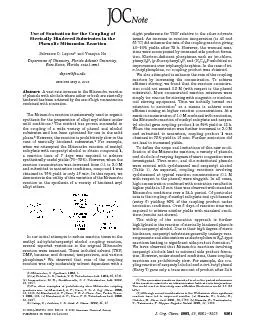


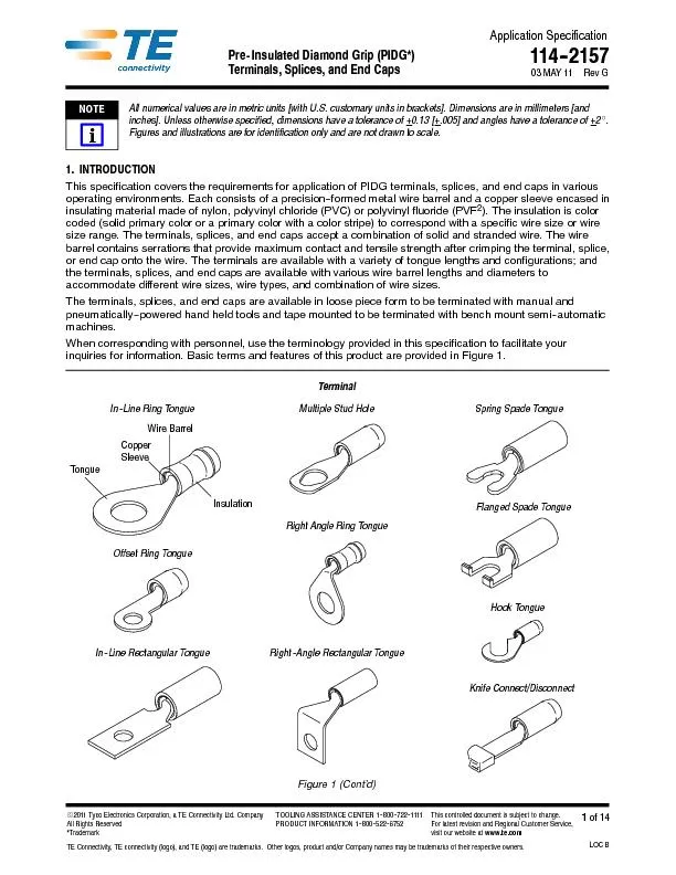
ApplicationSpecificationPre-InsulatedDiamondGrip(PIDG*)114--2157 of14LOCB2011TycoElectronicsCorporation,aTEConnectivityLtd.CompanyAllRightsReserved*TrademarkTEConnectivity,TEconnectivity(logo),andTE(logo)aretrademarks.Otherlogos,productand/orCompanynamesmaybetrademarksoftheirrespectiveowners.TOOLINGASSISTANCECENTER1--800--722--1111PRODUCTINFORMATION1--800--522--6752Thiscontrolleddocumentissubjecttochange.ForlatestrevisionandRegionalCustomerService,visitourwebsiteatwww.te.comTerminals,Splices,andEndCaps 03MAY11RevGAllnumericalvaluesareinmetricunits[withU.S.customaryunitsinbrackets].Dimensionsareinmillimeters[andinches].Unlessotherwisespecified,dimensionshaveatoleranceof+ 0.13[+ .005]andangleshaveatoleranceof+ Figuresandillustrationsareforidentificationonlyandarenotdrawntoscale.1.INTRODUCTIONThisspecificationcoverstherequirementsforapplicationofPIDGterminals,splices,andendcapsinvariousoperatingenvironments.Eachconsistsofaprecision--formedmetalwirebarrelandacoppersleeveencasedininsulatingmaterialmadeofnylon,polyvinylchloride(PVC)orpolyvinylfluoride(PVF).Theinsulationiscolor In--LineRingTongueIn--LineRectangularTongueOffsetRingTongueKnifeConnect/DisconnectHookTongueSpringSpadeTongueFlangedSpadeTongue CopperSleeve Insulation Terminal TongueWireBarrel 114-2157 Revof14 Figure1(End) WindowOpaqueInsulationWireBarrelCopperSleeve TransparentInsulationWindowEndCapInsulation ButtSplice2.REFERENCEMATERIAL2.1.RevisionSummaryRevisionstothisapplicationspecificationinclude:Changedcompanylogo2.2.CustomerAssistanceReferenceProductBasePartNumber51864andProductCode3022arerepresentativeofPIDGterminals,splices,andendcaps.Useofthesenumberswillidentifytheproductlineandexpediteyourinquiriesthroughaservicenetworkestablishedtohelpyouobtainproductandtoolinginformation.SuchinformationcanbeobtainedthroughalocalRepresentativeor,afterpurchase,bycallingPRODUCTINFORMATIONatthenumberatthebottomofpage1.2.3.DrawingsCustomerDrawingsforproductpartnumbersareavailablefromtheservicenetwork.IfthereisaconflictbetweentheinformationcontainedintheCustomerDrawingsandthisspecificationorwithanyothertechnicaldocumentationsupplied,callPRODUCTINFORMATIONatthenumberatthebottomofpage1.2.4.SpecificationsProductSpecification108--11023providestestandperformanceresultsforinsulatedterminalsandsplicesforClass1ENuclearapplications.2.5.InstructionalMaterialInstructionSheets(408--series)provideproductassemblyinstructionsortoolingsetupandoperationproceduresandCustomerManuals(409--series)providemachinesetupandoperationprocedures.Documentsavailablewhichpertaintothisproductare:408--1261HandCrimpingTools59239--4and59287--2408--1559HandCrimpingTools46121,47386,and47387408--1610T--HeadCrimpingTools59250and59275408--1632TerminalandSpliceCrimpingDies69344,47806--2,47807--1,47808--5,and47808--6408--2095HandCrimpingTool69710--1408--2423CrimpingDieAssembliesforTape--MountedPIDGTerminalsandSplices408--2498CrimpingHeadCrossReferenceforPneumaticTools408--2822CrimpingDieAssemblies59826--1,59827--1,and59828--1408--2823TETRA--CRIMP*HandCrimpingTool59824--1408--3295Preparing(Reel--Wrap)ReelofContactsforApplicatorTooling408--4099PneumaticTETRA--CRIMPAdapter679305--1408--4105StraightActionCrimper217200--[]408--7424CheckingTerminalCrimpHeightorGagingDieClosure408--8044MiniatureQuick--ChangeApplicatorforTape--MountedClosedBarrelTerminals408--8053MiniatureQuick--ChangeApplicators 114-2157 Revof14408--8082MiniatureQuick--ChangeApplicators(Side--FeedType)withAirFeed408--9252PRO--CRIMPER*IIIHandCrimpingTool58433--3408--9586PneumaticCrimpingHeads314269--1,314270--3,and314537--1408--9640CrimpQualityMonitorApplicatorsforSide--FeedandEnd--FeedApplications408--9816HandlingofReeledProducts409--1993AMP--TAPETRONIC*Machine69875409--5842AMP--O--LECTRIC*ModelGTerminatingMachine354500--1409--5862626PneumaticToolingAssemblies189721--[]409--5878AMPOMATOR*CLSIV+Lead--MakingMachines356500--[]2.6.StandardsandPublicationsMilitaryspecificationsprovideindustrytestandperformancerequirements.Documentsavailablewhichpertaintothisproductare:MIL--T7928/1,Terminal,LugandSplices,Conductor,CrimpStyle,CopperTerminal,Lug,CrimpStyle,Copper,Insulated,RingTongue,forThinWallWire,TypeII,ClassIfor105CTotalConductorTemperatureMIL--T7928/4,Terminals,LugandSplices,Conductor,CrimpStyle,CopperTerminal,Lug,Insulated,RingTongue,Bell--MountedTypeII,ClassIfor150CTotalConductorTemperatureMIL--T7928/5,Terminals,LugandSplices,Conductor,CrimpStyleMIL--T7928/6,Terminals,LugandSplices,Conductor,CrimpStyle,Splice,Electric,(Permanent,TypeII,Class1)for150CTotalConductorTemperatureMS17182,Terminal,Lug,CrimpStyle,Copper,Insulated(ServoComponents),TypeII,ClassIfor125TotalConductorTemperatureMS25036,Terminal,Lug,CrimpStyle,Copper,Insulated,RingTongue,BellMouthed,TypeII,Class1forCTotalConductorTemperatureMS25274,Cap,Electrical(WireEnd,CrimpStyle,TypeII,Class1)for105CTotalConductorTemperature3.REQUIREMENTS3.1.LimitationTheseterminalsandendcapsaresuitablefor300voltsmaximum,andthesplicesaresuitablefor600voltsmaximum.Theterminals,splices,andendcapshavingthefollowinginsulationcanwithstandthefollowingtemperaturerange:nylon--40to105C[--40to221PVC--10to90C[14to194--65to150C[--149to3023.2.StorageA.UltravioletLightProlongedexposuretoultravioletlightmaydeterioratethechemicalcompositionusedintheinsulation.B.ReelStorageTape--mountedreeledproductshouldbestoredhorizontallytopreventsaggingandpossiblestretchingordistortionoftheplastictapewhichcouldadverselyaffectfeedingoftheproductthroughthetooling.C.ShelfLifeTheproductshouldremainintheshippingcontainersuntilreadyforusetopreventinadvertentdamage.Theproductshouldbeusedonafirstin,firstoutbasistoavoidstoragecontaminationthatcouldadverselyaffectsignaltransmissions. 114-2157 Revof14D.ChemicalExposureDonotstoreproductnearchemicalslistedbelow.Theycouldcausestresscorrosioncrackingofproduct.AlkaliesAmmoniaCitratesPhosphatesCitratesSulfurCompoundsAminesCarbonatesNitritesSulfurNitritesTartrates3.3.WireSelectionandPreparationTerminalsandsplicesacceptsolidand/orstrandedwiresizes26through10AWGandendcapsacceptsolidand/orstrandedwiresizes22through10AWG.Thewiresizeusedmustbewithintherangestampedontheundersideoftheterminaltongueoronthecenterofthespliceorendcap.Generally,thestriplengthofthewireshouldbeequaltothewirebarrellengthplus0.76[.030].SpecificstriplengthsaregiveninFigure2.Conductor(StrandedShown)Note:NottoScale StripLength(SeeTable)Insulation WIRE TERMINAL,SPLICE, WIRESTRIPLENGTH SIZE(AWG) DIAMETERRANGE ORENDCAPINSULATIONCOLOR TERMINAL SPLICE ENDCAP 0.66--1.40[.026--.055] Yellow/Black 6.35--7.14[.250--.281] 26--24 Multiple Yellow 5.16--5.94[.203--.234] 4.37--5.16[.172--.203] 26--22 Multiple Yellow 3.96--4.78[.156--.188] 4.37--5.16[.172--.203] 4.78--5.56[.188--.219] 0.79--1.40[.031--.055] Blue 6.35--7.14[.188--.281] 2 4 2 0 M u l t i p l e White 24--20 Multiple Natural/White 4.78--5.56[.188--.219 5.56--6.35[.219--.250] 0.97--2.79[.038--.110] Red/Green 6.35--7.13[.250--.281] 2 2 1 6 M u l t i p l e Red 7.95--8.74[.313--.344] 22--16 Multiple Natural/Red 5.16--5.94[.203--.234 6.35--7.13[.250--.281] 1.17--2.79[.046--.110] Red/Red 6.35--7.13[.250--.281] 1.42--2.79[.056--.110] Red/White 6.35--7.13[.250--.281] 1.60--3.30[.063--.130] Blue/Blue 6.35--7.13[.250--.281] 1 6 1 4 M u l t i p l e Natural/Blue 16--14 Multiple Blue 5.16--5.94[.203--.234 6.35--7.13[.250--.281] 7.95--8.74[.313--.344] 16--14 Multiple Yellow/Black 7.93--8.71[.312--.343] 1.98--3.30[.078--.130] Blue/Green 6.35--7.13[.250--.281] 1 2 1 0 M u l t i p l e Natural/Yellow 12--10 Multiple Yellow 7.93--8.71[.312--.343 8.71--9.53[.343--.375] 8.74--9.53[.344--.375] 2.41--5.08[.095--.200] Yellow/Yellow 9.53--10.31[.375--.406] 3.02--5.08[.119--.200] Yellow/Brown 9.53--10.31[.375--.406] ContactPRODUCTINFORMATIONatthenumberonpage1foracceptableinsulationdiameterrangesangesLargesleeveterminaldesignedforClassIENuclearapplicationsForusewithheavy--dutyterminalshavinganinsulationthicknessof1.02--1.27[.040--.050]Figure2 114-2157 Revof14Thewireconductor(s)mustnotbenicked,scraped,orcutduringthestrippingoperation.3.4.WirePlacementThestrippedwiremustbeinsertedintothewirebarreluntilthewireinsulationisagainstthewirebarrelbutnotinsideit.Thewireinsulationmustbeinsidethemetalsleeve.Agapbetweenthewireinsulationandwirebarrelisallowed,butnottoexceedthedimensiongiveninFigure3. Figure3WireBarrel WireInsulationMayButtAgainst,ButNotEnter,WireBarrel 1.59[.062]MaximumGapWireInsulationMustBeInsideMetalSleeveSpliceInsulation TransparentInsulationWindowButtSpliceShown MetalSleeve 3.5.CrimpRequirementsA.CrimpHeightThespring--backoftheterminal,splice,orendcapinsulationpreventsanaccuratedirectmeasurementofcrimpheight.However,crimpingaslugofsolder(60%tinand40%lead)withadiameterslightlylargerthantheconductoroutsidediametercanverifypropertermination.Thecrimpheightoftheresultingsolderslugcanbecheckedwithastandardmicrometerorcomparator.Themeasurementmustbemadeoverthemostcompressedareaofthesolderslug.SeeFigure4.Sometoolingwithmultiplecrimpingchambersformanembosseddotcodeintheterminal,splice,orendcapinsulationthatindicateswhichcrimpingchamberwasused.Thisdotcodecanbeusedasavisualinspectiontoensurethatthecorrectwiresizeandcrimpingchamberwereused.Theresilienceofthespliceinsulationpreventsaccuratedirectmeasurementofcrimpheight.Crimpheightcanbeobtainedbymeasuringacrimpedsolderslug(60%tinand40%lead)withadiametercomparabletothewiresize.Theslugmustbemeasuredoverthemostcompressedareaoftheslugwithastandardmicrometerorcrimpheightcomparator(referto408--7424forspecificinstructions).ThesolderslugdiameterandcrimpheightmustbewithinthedimensionsprovidedinFigure4.B.WireBarrelCrimpProfileandLocationThewirebarrelcrimpproducedbythetooling(dies,heads,handtools,pneumatictools,ormachines)mustbeeitheraconfinedcrescentcrimpwhichappearsasadepressedovalshapeoraflatrectangularcrimpoverthecenterofthewirebarrel.Thecrimpmustbeevenlyformed.RefertoFigures4,5,and11.Crescentcrimptoolingproducesthecrescentcrimp,andTETRA--CRIMPtoolingproducestheflatrectangularcrimp.Foratooling--to--crimpprofilecross--reference,refertoFigure10.C.DotCodeThedotcodeontheinsulationmustbewellformedandcorrespondwiththewiresizeorcolorcodemarkingonthecrimpingchamberofthetoolingused.SeeFigures4and5.D.BellmouthsThereshallbenorearbellmouth.ThefrontbellmouthshallbeevidentonthetopandbottomofthewirebarrelasshowninFigure5.AlsoseeFigure11. 114-2157 Revof14 MicrometerorComparatorCrescentCrimp(DepressedOvalShape)FlatRectangularCrimp CenterofMostCompressedArea(RefertoTableforCrimpHeight) DotCode(1DotShown) SolderSlugProducedbyCrescentCrimpToolingProducedbyTETRA--CRIMPTooling r i m p I n s n U s i n g M i c r o m ete r a r a i r e B a r r e l C r i m p P r a n dLoc i o n DotCode(1DotShown) CrimpEvenlyFormedOverCenterofWireBarrel SOLDERSLUG WIRESIZE TERMINAL,SPLICE, CRIMPHEIGHT (AWG) INSULATIONCOLOR DIAMETER CRESCENTCRIMP FLATRECTANGULAR (DepressedOvalShape) CRIMP Yellow/Black 26--24 Yellow 26--22 Yellow 1Dot 3.18[.125 1.60--1.75[.063--.069] Yellow/Blue White 24--20 Natural/White 2Dots 3.18[.125 2.26--2.41[.089--.095] Red/Green 1Dot Red 22--16 Natural/Red 1Dot 3.18[.125 2.77--2.92[.109--.115] 1.98--2.18[.078--.086 Red/Red 1Dot Red/White 1Dot Blue/Blue 2Dots 3.18[.125 3.02--3.18[.119--.125] 2.34--2.54[.092--.100 Blue 16--14 Natural/Blue 2Dots 4.76[.187] 3.02--3.18[.119--.125] 2.34--2.54[.092--.100] Blue/Green 2Dots 16--14 Yellow/Black 1Dot Yellow/Yellow 1Dot Yellow 6.35[.250] 4.29--4.45[.169--.175] 3.25--3.45[.128--.136] 12--10 Natural/Yellow 1Dot Yellow/Brown 1Dot Forusewithheavydutyterminalshavinganinsulationthicknessrangeof1.02--1.27[.040--.050].Figure4 114-2157 Revof14Figure5WireSizeMarkingMatchesWireSize OverstressMarksNotApparentonInsulation WireConductor(s)VisibleWithinThisArea(ExceptSpliceandEndCap,SeeDetailAandDetailB) FrontBellmouthEvident(TopandBottomofWireBarrel)DotCode(1DotShown)isWellFormedandCorrespondsWithCrimpingChamberofToolingUsed WireInsulationInsideMetalSleeveButNotInsideWireBarrel NoFlashinThisArea WireBottomedinEndCapCutawayShowforClarity NoRearBellmouth WireFlushtoEndofWireBarrelorBottomedonStopInsideCenterofSplice Note:TerminalShownSameAppliestoSpliceandEndCapDetailBEndCapDetailASplice E.FlashThereshallbenoflashorextrudedinsulationmaterialvisibleinthemostcompressedareaofthewirecrimp.SeeFigure5.F.Terminal,Splice,orEndCapInsulationTheinsulationoftheterminal,splice,orendcapmustnotbecutorshowunevenstressmarksorhighlightedmarksontheinsulation.SeeFigure5.G.WireLocation1.TerminalsshallhavethewireendsflushorextendedslightlybeyondtheendofthewirebarrelasshowninFigure5.2.Splicesshallhavetheendofthewirelocatedagainstthewirestopinsidethecenterofthesplice.3.Endcapsshallhavetheendofthewirebottomedintheendcap.H.InsulationCrimpCheckTheinsulationcrimpmustcapturethewireinsulation.Thewireinsulationmustnotbecrimpedinsidethewirebarreloftheterminal,splice,orendcap.Thewireinsulationmustbeinsidethemetalsleevetoprovidestrainreliefforthewire.SeeFigure5.Theholdoftheinsulationcrimpcanbetestedbyusingthebendtestwhich,ifsuccessful,indicatesthattheholdisnottooloose.Thebendtestmustbeperformedasfollows:1.Usinganunstrippedwire,makeatestcrimp 2.Holdtheterminal,splice,orendcapinonehand.Usethesideofonefingerontheotherhandatapproximately76[3]topushthewireup90anddown180,onetimeeach.RefertoFigure6.Ifthewireinsulationcomesoutduringthebendtest,theinsulationcrimpisnottightenough,andthetoolingmustbeadjustedtoproduceatighterinsulationcrimp.Figure8,DetailAshowsacrimpthatistooloose,providinglittleornosupportforthewire. 114-2157 Revof14Ifthecrimppassesthebendtest,theinsulationcrimpmustbetestedbypullingthewirefromtheterminal,splice,orendcap.Ifthewireinsulationisonlyslightlydeformed,thecrimpiscorrect.Figure8,DetailBshowsadesiredcrimp,providingadequatesupportwithoutdamagetoeithertheinsulationorthewireconductor(s).Ifthereisvisibledamage,suchastearingorpiercingoftheinsulation,thecrimpistootight,andthetoolingmustbeadjustedtoproducealooserinsulationcrimp.Figure8,DetailCshowsacrimpthatistootight,damagingtheinsulationandpossiblybreakingwireconductor(s)orreducingcircularmilarea(CMA)bywireextrusion.Figure6 HoldHere Note:NottoScaleBendTest(TestCrimpUsingUnstrippedWire) 76.2[3](Approx) 1stPush 2ndPush 3.6.TensileStrengthCrimpedterminals,splices,orendcapsshouldholdthewireconductor(s)firmlyandhaveapull--testtensilevaluemeetingthatspecifiedinthetableinFigure7.Adjusttensiletestingmachineforheadtravelof25.4[1.0]perminute.Directlyandgraduallyapplyforcefor1minute.WIRESIZE TENSILEFORCE(PullTest)Newtons[lb--force] (AWG) COMMERCIALREQUIREMENTS MILITARYREQUIREMENTS 13.4[3] 31.1[7] 22.3[5] 44.5[10] 35.6[8] 66.7[15] 57.9[13] 84.5[19] 89.0[20] 169.0[38] 133.5[30] 222.5[50] 222.5[50] 311.5[70] 311.5[70] 489.3[110] 356.0[80] 667.2[150] Figure7 114-2157 Revof14Figure8 DetailATooLooseDetailBCorrectDetailCTooTight MetalSleeveTerminal,Splice,orEndCapInsulationWireInsulation Cross-SectionofInsulationCrimpatWireEndofTerminal,Splice,orEndCap(IllustrationsRepresentUppermostWireInsulationRangeofTerminal,Splice,orEndCap(ThinnerWireInsulationMayAppearSlightlyDifferent,ButWillPerformtheSame,RefertoFigure2) 3.7.BendAllowanceUpwardanddownwardbendoftheterminatedterminal,splice,orendcapmustbewithinthetoleranceprovidedinFigure9.Figure9 TerminalSpliceDatumLineDatumLineCenterofSplice EndCap DatumLine CenterofCrimp CenterofCrimp 3.8.RepairDamagedordefectiveterminal,splice,orendcapmustnotbeused.Ifdamageisevident,theterminal,splice,orendcapshouldbecutfromthewireandreplacedwithanewone.Crimpedterminals,splices,orendcapsMUSTNOTbere--terminatedorre--usedbyremovingthewire. 114-2157 Revof144.QUALIFICATIONSMost,butnotall,PIDGterminals,splices,andendcapsareListedbyUnderwritersLaboratoriesInc.(UL)inFileE13288andCertifiedbyCSAInternationalinFileLR7189.Todeterminewhetheraterminal,splice,orendcap(identifiedbypartnumber)meetstherequirementsofanagency,contactPRODUCTINFORMATIONatthenumberatthebottomofpage1.5.TOOLINGHandtoolsformanualapplicationofloosepieceterminals,splices,orendcaps,andautomaticandsemi--automaticmachinesforpowerassistedapplicationoftape--mountedterminals,splices,orendcapsareavailabletocoverthefullwiresizerange.ToolingpartnumbersandinstructionalmaterialpackagedwiththetoolingareshowninFigure10.Selectionoftoolingwilldependontheterminal,splice,orendcaprequirementssuchasquantityofterminations,operatortrainingandskill,andtheavailablesupportequipment(electrical,pneumatic,etc.)intheworkarea.Modifieddesignsandadditionaltoolingconceptsmaybeavailabletomeetotherproductionrequirements.Foradditionalinformation,contactoneoftheservicegroupsatthebottomofpage1.5.1.HandToolsHandtoolsconsistingofahandleassemblywithintegralfixedjawsordiesandhandtoolsthatacceptvariousdieassembliesareavailableforloosepieceterminals,splices,orendcaps.Bothtypesfeaturearatchettoensurefullcrimpingpressureisappliedtotheterminal,splice,orendcap.5.2.DieAssembliesDieassembliesareprecisiontoolsthatformthewirebarreloftheterminal,splice,orendcapontotheconductor(s)ofthewireandformtheoptimumcrimpheight.Thedieassembliesconsistofstationaryandmovablediesthataredesignedforaspecificwiresizeandterminal,splice,orendcap.A.LoosePieceTerminal,Splice,orEndCapThesedieassembliescanbeusedineithermanualorpowerassisttools.B.Tape-MountedTerminal,Splice,orEndCapThesedieassembliesaredesignedforuseinapplicatorsinstalledinpowerunits.5.3.ApplicatorsApplicatorsareusedinpowerunitsforlargeproductionapplications.Theyfeatureanautomaticfeedmechanism,adjustablecrimpheightpads,andprecisioncrimpingdies.Theyhavebeendesignedtosimplifytoolingchangesandavoidunnecessaryduplicationofpowerunits.5.4.626PneumaticToolingSystemThispneumaticallyoperatedtoolingsystemwillcrimpthefullwiresizerangeoftheterminal,splice,orendcap.Thesystemisapneumaticpowerunitavailablewithalogiccontrolforfootpedaloperationorwithoutfootpedalforhandoperation.Itisdesignedtoacceptvarioustypesofcrimpingheads,includingthosethatwillacceptdieassembliesforloosepieceterminals,splices,orendcaps.5.5.PowerUnitsPowerunitsprovidetheforceneededtooperatetheapplicator.A.Bench-MountedAMP--O--LECTRICModelGterminatingmachineandAMP--TAPETRONICmachinearedesignedtoaccepthand--fedpre--strippedwires.B.FloorStandingTheAMPOMATORCLSIV+lead--makingmachinecanbesetuptoautomaticallycutthewiretolengthandterminateitatahighrateofspeed. 114-2157 Revof14 PneumaticCrimpingHeads(RefertoTable)(408--9586) StraightActionCrimper217200--[](AcceptsAllDieAssembliesListedinTable)(408--4105) TETRA--CRIMPHandCrimpingTool(408--2823)PRO--CRIMPERIIIHandCrimpingTool(408--9252)HandToolsandDieAssemblies(RefertoTableforPartNumbers)T--HeadHandTools(T--HDHT)(408--1610)DoubleActionHandTools(DAHT)(408--1559)626PneumaticToolingSystemTerminalandSpliceDieAssemblies(408--1632)HeavyHeadHandTools(HHHT)(408--1261) HandCrimpingTool69710--1(AcceptsAllDieAssembliesListedinTable)(408--2095) TETRA--CRIMPPneumaticAdapter(RefertoTable)(408--4099) 626PneumaticToolingAssemblies189721--[](409--5862)ToolHolderAssembly189766--[](Small) P i r m i n a l , r E n ToolHolderAssembly189928--1(StraightAction)ToolHolderAssembly189767--[](Large) HANDTOOL PNEUMATICTOOLING WIRESIZE(AWG) T--HDHT TETRA--CRIMPHandTool PRO--CRIMPERHandTool CrimpingHead TETRA--CRIMPAdapter DIEASSEMBLY 26--22 46121 59275 314537--1 0----0 22--18 22--16 47386 59250 59824--1 58433--3 314270--3 47806--2 16--14 59250 59824--1 58433--3 314269--1 47807--1 16--14and12--10 59824--1 58433--3 59239--4or59287--2 679305--1 47808--6or47808--5 Forusewithterminalshavinganinsulationthicknessrangeof0.51--0.84[.020--.033].Forusewithheavydutyterminalshavinganinsulationthicknessof1.02--1.27[.040--.050].Forusewithwirehavingamaximuminsulationdiameterof7.62[.300].roducesCrescentCrimpProducesFlatRectangularCrimpForusewithTool69710--1orCrimper217200--[]Figure10(Contd) 114-2157 Revof14DieAssemblies69872,69873,69874,69877,and69897(408--2423)DieAssemblies59826--1,59827--1,and59828--1(408--2822)AMP--TAPETRONICMachine69875(409--1993) AMPOMATORCLSIV+Lead--MakingMachine356500--[](409--5878) AMP--O--LECTRICModelGTerminatingMachine354500--1(409--5842) MiniatureQuick--ChangeApplicator567200--3(408--8082)MiniatureQuick--ChangeApplicator687658--1(408--8044) Tape-MountedTerminal,Splice,orEndCapPowerUnitsDieAssembliesandApplicators APPLICATOR WIRESIZE(AWG) DIEASSEMBLY AMP--TAPETRONICMachine AMP--O--LECTRICModelGTerminatingMachine AMPOMATORCLSIV+Lead--MakingMachine 26--22 69877 22--16 or59826--1 16--14 or59827--1 IncludedwithMachine 567200--3 687658--1 16--14and12--10 59828--1or69897 Forusewithterminalshavinganinsulationthicknessrangeof0.51--0.84[.020--.033].Forusewithheavydutyterminalshavinganinsulationthicknessof1.02--1.27[.040--.050].Forusewithwirehavingamaximuminsulationdiameterof7.62[.300].ProducesCrescentCrimpProducesFlatRectangularCrimpFigure10(End) 114-2157 Revof146.VISUALAIDFigure11showsatypicalapplicationofPIDGterminals,splices,andendcaps.Thisillustrationshouldbeusedbyproductionpersonneltoensureacorrectlyappliedterminal,splice,orendcap.ApplicationswhichDONOTappearcorrectshouldbeinspectedusingtheinformationintheprecedingpagesofthisspecificationandintheinstructionalmaterialshippedwiththeproductortooling.FIGURE11.VISUALAID(CONTD) ENDOFTERMINAL,SPLICE,ORENDCAPMUSTNOTBEBENTORDEFORMED CRIMPMUSTBEEVENLYFORMEDACROSSCENTEROFWIREBARREL INSULATIONOFTERMINAL,SPLICE,ORENDCAPMUSTBEFORMEDOVERWIREINSULATION WIREMUSTBEVISIBLEATENDOFWIREBARRELIFAPPLICABLE,DOTCODEMUSTBEWELLFORMEDANDCORRESPONDWITHWIRESIZEMARKINGONTOOLINGTERMINAL,SPLICE,ORENDCAPMUSTBESTRAIGHTANDNOTTWISTEDALONGAXISINSULATIONOFTERMINAL,SPLICE,ORENDCAPMUSTBEEVENLYFORMEDWITHOUTOVERSTRESSMARKS WIREINSULATIONMUSTBEINSIDEMETALSLEEVEOFTERMINAL,SPLICE,ORENDCAPINSULATIONOFTERMINAL,SPLICE,ORENDCAPMUSTNOTBECUTORTORN FRONTBELLMOUTHMUSTBEEVIDENT WIREMUSTBEBOTTOMEDINENDCAP EACHWIREMUSTBEFLUSHTOENDOFWIREBARRELORBOTTOMEDONSTOP 114-2157 Revof14FIGURE11.VISUALAID(END) PROPERCRIMPCRIMPCENTEREDONWIREBARREL FRONTBELLMOUTHONTOPOFINSULATION FRONTBELLMOUTHONTOPANDBOTTOMOFWIREBARRELSMALLAMOUNTOFSPACEBETWEENWIRECONDUCTOR(S)ANDWIREBARREL DetailADetailB(InsulationandMetalSleeveRemoved)IMPROPERCRIMPCRIMPTOOFARFRONTONWIREBARREL NOBELLMOUTHONTOPOFWIREBARRELNOSPACEBETWEENWIRECONDUCTOR(S)ANDWIREBARREL FRONTBELLMOUTHONTOPOFINSULATIONTOOLARGE NOBELLMOUTHONBOTTOMOFWIREBARRELTOOMUCHSPACEBETWEENWIRECONDUCTOR(S)ANDWIREBARRELCRIMPTOOFARBACKONWIREBARREL DetailADetailB(InsulationandMetalSleeveRemoved)DetailADetailB(InsulationandMetalSleeveRemoved) NOBELLMOUTHONTOPOFINSULATION