
Steve Sandler Picotest stevepicotestcom 14803750075 What are sensitive circuits Many low power circuits are hypersensitive to power supply noise Examples of hypersensitive circuits include clock oscillators XOs low noise amplifiers LNAs phase locked loops PLLs mixer ID: 1031503
Download Presentation The PPT/PDF document "Designing Power For Sensitive Circuits" is the property of its rightful owner. Permission is granted to download and print the materials on this web site for personal, non-commercial use only, and to display it on your personal computer provided you do not modify the materials and that you retain all copyright notices contained in the materials. By downloading content from our website, you accept the terms of this agreement.

1. Designing Power For Sensitive Circuits Steve Sandler, Picotest steve@picotest.com +1-480-375-0075
2. What are sensitive circuits?Many low power circuits are hyper-sensitive to power supply noise. Examples of hyper-sensitive circuits include clock oscillators (XOs), low noise amplifiers (LNAs), phase locked loops (PLLs), mixers and precision voltage references to name just a few.
3. Sensitivity to power supply noise
4.
5. Defining Sensitivity
6. Not all sensitive circuits are sensitive
7. Noise Density 3 Voltage RegulatorsIntegrated noise voltage 1kHz to 100kHz≈ 1uVpp≈100uVpp≈750uVpp
8. Switching Regulator Noise DensityThe switching regulator noise density is a little above 1uV/ in the highlighted frequency range
9. Phase Noise 3 Voltage Regulators
10. Assessing the Damage
11. Simplest Noise Filter Regulation and noise are not the same thing and counterintuitively they oppose each other How much voltage can you give up?
12. Determining the CapacitorRequired attenuation
13. 33uF/30mΩ ESR + 2.4Ω Filter
14. 1kHz RBWUnexpected Noise – 2.8MHz POL
15. Why The Low Frequency Noise?1kHz RBW) This is in very good agreement with the signal source analyzer noise density measurement
16. The modulation noise is accounted forDespite the 2.8MHz switching frequency it’s the 10kHz range that defines the filterRequired attenuation
17. About Ferrite Beads IF R approaches zero then NO INDUCTANCE ALLOWEDFor Q=0.5
18. Assess over the entire operating current rangeBead datasheets generally include DCR and high frequency resistance, but look for Inductive reactance and DC Bias data or measure it yourself Courtesy of Wurth Electronik
19. 0.3, 1.3 and 2.3Ohm resistanceWithout the resistanceSignificant peaking will occur
20. “RF” Ultra-Low-Noise OptionsThe precision ultra-low-noise voltage regulator offers precision in the output voltage and low noiseBUTCount the capacitors!Is this better or just different?Precision voltage vs ultra-low noise
21. Top TipsInclude phase noise and jitter in your simulationsHigher value caps are generally better than lower value caps Low current bias also needs to be filtered.
22. Not all regulators are created equalMeasure LOTS of them!
23. Watch the coaxial cables and power interconnects alsoConsider all the ways noise gets in
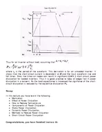
24. Thanks for Attending this Session!Connect with me on LinkedIn or via email at Steve@Picotest.comLearn more at www.picotest.com/blogIn this session I sharedHow to determine the circuit sensitivity to power supply noiseHow to choose the best voltage regulatorHow to design an optimum power supply noise filterA few of my top tips for designing power for sensitive circuits