
multislice CT scanning ImPACT ImPACT technology CT scanning has been recognised as a high radiation dose modality when compared to other diagnostic Xray techniques since its l The aim of this le ID: 945922
Download Pdf The PPT/PDF document "Radiation dose issues in" is the property of its rightful owner. Permission is granted to download and print the materials on this web site for personal, non-commercial use only, and to display it on your personal computer provided you do not modify the materials and that you retain all copyright notices contained in the materials. By downloading content from our website, you accept the terms of this agreement.


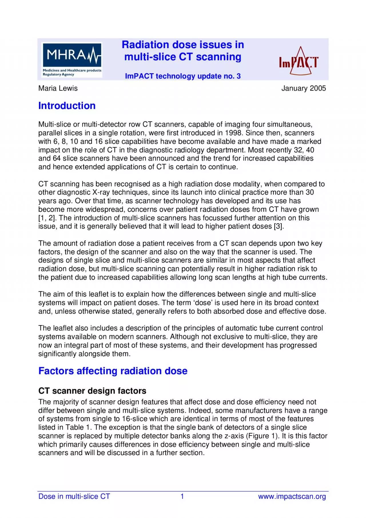
Radiation dose issues in multi-slice CT scanning ImPACT ImPACT technology CT scanning has been recognised as a high radiation dose modality, when compared to other diagnostic X-ray techniques, since its l The aim of this leaflet is to explain how the differences between single and multi-slice systems will impact on patient doses. The term ‘dose’ is used here in its broad context Factors affecting radiation dose CT scanner design factors The majority of scanner design features that affect dose and dose efficiency need not differ between single and multi-slice systems. Indeed, some manufacturers have a range of systems from single to 16-slice which are identical in terms of most of the features listed in Table 1. The exception is that the single bank of The graphs in Figure 4 demonstrate the effect on the absorbed dose of a reduced z-axis geometric efficiency at narrow collimations. The benefit of acquiring a larger number of simultaneous, narrow slices is demonstrated in Figure 4b. Figure 4: Data for typical multi-slice CT scanner showing dose relative to 20mm collimation plotted against (a) collimation, and (b) imaged slice width 0.81.01.21.41.61.82.02.22.40102030collimation (mm)relative dose 0.81.01.21.41.61.82.02.22.40246810imaged slice width (mm)relative dose scanner operating in 4-slice mode scanner operating in 16-slice mode (a) (b) Detector array geometric efficiency (GE) The total detector area consists of detector material and septa between the detector elements both in the scan (x-y) plane and, on multi-slice scanners, in the axial (z-axis) direction. Generally, as the number of simultaneously acquired slices increases, the size of the
detector elements in the z-direction decreases. This leads to an increase in the number of septa and therefore a reduction in detector array geometric efficiency (Figure 5). The definition of detector array geometric efficiency is: active detector areaDetector array GE total detector area An illustration of this effect is shown in Table 4 for the Philips Mx8000 range of scanners [6]. In this example the reduction in efficiency when moving from a 2-slice to a 16-slice system is only around 6%. This figure will vary with detector array design, with a trend towards lower efficiency values as the number of detectors per imaged length increases. Figure 5: Diagram of section of detector array from (a) an 8-slice and (b) a 16-slice CT scanner. The 16-slice scanner has approximately twice the number of septa along the z-axis (a)(b) z-axis x-axis (a)(b) z-axis x-axis Dose in multi-slice CT 5 www.impactscan.org Table 4: Detector array efficiency for the Philips Mx8000 scanner range Scanner modelNo. of detector banksz-axis coverage (mm)Detector array efficiency (%)2-slice220804-slice8207816-slice242475 Considerations for helical scanning Helical pitch On multi-slice scanners, as on single slice systems, the absorbed radiation dose is inversely proportional to pitch if the tube current – time product (mAs) and tube potential (kV) are kept constant i.e. the dose will be halved if the pitch is doubled. Due to the nature of the reconstruction method used, on single slice scanners the imaged slice width increases as the pitch increases. As a result, noise on single slice systems remains constant with changing pitch. However, on multi-slice scanners differen
t image reconstruction methods are used [7], and some of these allow for the imaged slice width to remain constant with pitch. In these circumstances the noise will increase as the pitch increases. Some multi-slice scanner manufacturers automatically adjust the tube current to compensate for changes in pitch. This maintains a constant noise and dose with changing pitch. A parameter termed ‘effective mAs’ or ‘mAs per slice’ is sometimes quoted on multi-slice scanners. This quantity is designed to reflect the effect on the average absorbed dose in the scanned volume when the pitch is changed.The adjusted mAs value is obtained by dividing the true mAs per rotation by the pitch value. When making dose calculations it is important to be aware whether true mAs or ‘effective mAs’ is being quoted. The two equations below show how the average absorbed dose within the scanned volume, CTDI vol , is calculated from the n CTDI w , the average absorbed dose in the scan plane per mAs, from either the true mAs or the ‘effective mAs’. volnwmAsCTDI = CTDI x pitch volnw CTDI = CTDIx 'effective mAs' An illustration of the relationship between pitch, mAs, ‘effective mAs’ and CTDI vol is given in Table 5. Dose in multi-slice CT 6 www.impactscan.org Table 5: Relationship between pitch, mAs, ‘effective mAs’ and CTDI vol a. for constant mAsPitchx*mAs per rotation'effective mAs' or 'mAs per slice'Relative CTDIvolAxial scan1001001.00.51002002.011001001.01.5100670.672100500.5b. for constant "effective mAs"Pitchx*mAs per rotation'effective mAs' or 'mAs per slice'Relative CTDIvolAxial scan1001001.00.5501001.0110
01001.01.51501001.022001001.0 *Pitch x = table travel per rotation , as defined in ImPACT Technology Update No.1 [8] X-ray beam collimation Additional rotations for helical interpolation In helical scanning, additional information is required at each end of the planned image volume in order to provide interpolation data for the first and last images. On single slice scanners a half, or one, extra rotation is generally required at each end of the imaged volume. On multi-slice scanners the number of additional rotations required can potentially depend on a number of factors such as the interpolation method, the pitch and the reconstructed image width [9]. Each additional rotation on a multi-slice scanner generally contributes a greater percentage to the dose than that on a single slice scanner because the total collimated beam width is usually greater. This is shown diagrammatically in Figure 6 where the planned scanned length is equal for both the single and multi-slice scanner. When planning scan lengths to avoid sensitive organs such as eye lenses or gonads, the additional rotations associated with helical scanning should be borne in mind. The additional dose will be particularly significant for short scan lengths and in these situations it may be preferable to perform the scan in conventional slice by slice mode which does not require the extra rotations. As an example, for a collimated X-ray beam of 20 mm with one extra rotation at each end of a scan run, the increase in effective dose, relative to axial scanning, will be 10% for a scan length of 400 mm, and 40% for a scan length of 100 mm. This compares to increased dose figures of 2.5% a
nd 10% respectively, for the same scan lengths on a single slice scanner, assuming half an extra rotation at each end of the scan run. Dose in multi-slice CT 7 www.impactscan.org Figure 6: Additional irradiation outside the imaged volume (a) a single slice and (b) a multi-slice CT scanner operating in helical mode Planned scan length Planned scan length Planned scan length Planned scan length Planned scan length Planned scan length Planned scan length Planned scan length (a) (b) Dose optimisation On any CT scanner the patient dose is highly dependent on the scan parameters used: kV, mA, rotation time, focal spot size, scan field of view, slice width and pitch. On multi-slice scanners there is the additional variable of X-ray beam collimation, as the same imaged slice width can be achieved from data acquired at a number of collimations. All these parameters must be carefully selected so that the given diagnostic requirements are met at the optimum level of radiation dose. In addition to the scan parameters, the reconstruction parameters such as the reconstruction matrix, reconstruction field of view and reconstruction algorithm must be considered. Although these do not affect dose directly, they may have an indirect effect by altering the image characteristics. Automatic tube current control A key parameter affecting dose to the patient is the selected tube current – time product (mAs). Automatic exposure control systems (AECs) have been an integral component of conventional X-ray units for many years. They operate by adjusting the length of the exposure, to produce X-ray films with a consistent level of optical density, reg
ardless of the patient size. This avoids over- and under-exposures of the radiographic film and the necessity for repeat examinations. Digital systems, such as CT scanners, do not incur an image quality penalty at high exposures, and mAs values have, until recently, always been selected manually by the operator. Manufacturers generally recommend tube current and time settings for different examinations for a standard sized patient and the operator must decide whether, and if so, by how much, to adjust these settings to take into account variations in patient size. More recently, following concerns about dose levels in CT, particularly to paediatric patients [10], age or weight based tables of exposure settings are often provided as a guide to the user. Over the last few years manufacturers have developed techniques for AEC in CT. On CT scanners the approach is to vary the tube current (mA). The overall aim of these systems is to achieve a more consistent level of image quality from patient to patient and also to optimise the use of X-rays, thereby reducing dose. The attenuation of the X-ray beam increases with the thickness of material in its path, and for approximately every 4 cm of soft tissue, the X-ray beam intensity halves. In order Dose in multi-slice CT 8 www.impactscan.org to achieve the same transmitted X-ray intensity, and thereby the same level of image noise, changing from a 16 cm to a 20 cm diameter phantom requires a doubling of the mA. Changing from a 32 cm to a 48 cm phantom, the mA should, in theory, be increased by a factor of 16. Systems which automatically adapt the overall tube current based on actual patient attenuation remove the gues
swork from selecting the appropriate mA setting. The adjustment of tube current can be considered on three levels. At the first level the mA is adjusted to take account of overall patient size (Figure 7a).The aim is to have a similar value of image noise for patients of different sizes. If used in isolation, this level of AEC maintains the same mA throughout the scan. However it is usually used in combination with the other levels of mA adjustment described below, which take into account attenuation variations within the patient. Figure 7: Automatic adjustment of tube current to account for (a) overall patient size, (b) attenuation variations along patient’s long axis and (c) varying attenuation throughout a rotation high mA low mAz-position mA z-position mA mA high mA low mAz-position mA z-position mA mA high mA low mAz-position mA z-position mA mA high mA low mA high mA high mA low mA low mAz-position mA z-position mA mA mA mA z-position mA mA z-position mA z-position mA z-position mA z-position mA mA mA mA mA (a) (b) (c) At the second level of automatic mA control, z-axis modulation, the mA is varied on a rotation by rotation basis to account for variations in attenuation along the patient’s long axis (z-axis) (Figure 7b). With this type of tube current control, the mean level of image noise within a slice should remain approximately constant for different positions along the z-axis. At the third level of automatic mA control, angular modulation, the mA is varied during the course of each tube rotation to compensate for the varying attenuation at different angles through the patient (Figure 7c). At some anatomical levels, e.g. the shoulders an
d pelvis, there is a considerable difference in attenuation between the lateral and anterior-posterior (AP) directions through the patient. The highest tube current is usually required for the lateral projections. Using this technique, a more uniform level of image noise is obtained across the imaged plane, and a given noise level can be achieved at a lower average mA. Automatic mA adjustment requires prior knowledge of the attenuation characteristics of a patient. The attenuation information to adapt the mA for patient size is obtained from the planning scan projection radiograph (SPR), referred to by different manufacturers as ScoutView, Scanogram or Topogram. The SPR information is also used to adjust the mA for each rotation. There are two different methods currently used for obtaining Dose in multi-slice CT 9 www.impactscan.org information to vary the mA during a rotation. The first method uses the SPR to calculate the relative AP and lateral patient dimensions in each rotation. The mA is then varied sinusoidally to best match this ratio. The second method uses ‘online’ data from the preceding 180° of rotation to modulate the mA. When using these AEC systems, some way of prescribing the mA, and thereby the desired level of image quality, must be adopted. Manufacturers have approached this using a variety of methods. On some systems the mA that would be used without AEC on an standard-sized patient is input, and this value is used as the base-line for calculating the mA needed to obtain the same noise level for different patient sizes. Other systems require an ‘image quality’ index to be input. This index is usually related to the no
ise value (standard deviation of the CT numbers in a water phantom), and the mA is adjusted to maintain this prescribed noise level for all patient sizes. A third approach is to select a ‘reference image’ with the required level of image quality for a particular examination. This image is then used to adjust the mA such that the same level of image quality is achieved for each patient. In addition to the various methods for prescribing the tube current there is usually an option to set the upper and lower limits of the mA used by the AEC system. Automatic adjustment of tube current is not only a useful dose reduction tool but can also lead to benefits in image quality. It should result in more consistent image quality from patient to patient, from slice to slice, and within a slice. Modulation of mA throughout a rotation can also reduce streaking artefacts caused by low photon flux in the lateral projections of anatomical areas such as the shoulders and pelvis. An added advantage of automatic mA control is that since it is designed to use lower overall mAs values, the heat capacity of the tube is preserved, allowing for longer scan lengths if these are deemed necessary, and for a longer tube life. However, it is also important to note that although AEC systems are often marketed as dose-reduction tools, it is perfectly possible to operate them at a higher radiation dose then would be obtained without their use. Careful prescription of the mAs or image quality is needed to ensure that doses are optimised and within reference dose values [11]. Manufacturers are in the process of further developing their AEC systems. Different scanner models within a range may have different
levels of AEC available. The most advanced systems are usually offered on the premium line scanners, and the current status of these is shown in Table 6. Dose in multi-slice CT 10 www.impactscan.org Table 6: Capabilities of AEC packages available on top-of-the-range 16-slice CT scanners Manufacturer NameGE SmartmApatient size z-axis angular modulation* noise index specified by user SPR angular modulation: sinusoidal PhilipsDoseRight ACS and DOMpatient size (ACS) angular modulation (DOM) reference image with desired noise level selected by userSPR angular modulation: online, based on previous 180° SiemensCAREDose 4Dpatient size z-axis angular modulation mA for standard patient specified by user SPR angular modulation: online, based on previous 180°ToshibaSUREExposurepatient size z-axisnoise index specified by userSPR* On Li g htSpeed Pro16 onl y Level of automatic mA control Attenuation calculation Prescription of mA Appropriate image quality Automatic exposure of tube current is an invaluable dose optimisation tool but relies on the operator selecting either the mA for a standard patient or the required level of noise for a given examination. Because CT does not carry an image quality penalty for over-exposure, there has been a tendency to err on the side of lower than necessary noise levels and hence higher doses. The current challenge in CT is to identify an appropriate image quali
ty. This is the optimal value of noise for an examination i.e. the level at which a diagnosis can reliably be made at a minimum dose level. A relatively new approach to determining these optimal noise levels is through the addition of simulated noise to images obtained at higher mAs values. Images from the same patient at a range of noise levels can then be viewed and scored for diagnostic quality, without subjecting the patient to multiple exposures. A number of studies using this approach have been undertaken and suggest that, in some cases, it is possible to significantly reduce mAs values without affecting the diagnostic quality of the scan [12, 13]. ECG-gated cardiac studies Cardiac imaging is one of the most rapidly developing areas of CT. Due to the rapid motion of the heart, images would suffer from severe blurring if standard reconstruction methods were used. To overcome these difficulties, techniques have been developed to produce images using data from just a fraction of the cardiac cycle. This is achieved in conjunction with ECG monitoring, so that only data acquired in mid to late diastolic phase, where there is least cardiac motion, is used in image reconstruction. One way in which significant dose reduction can be achieved is by using the ECG information to control the tube current so that the selected mA is maintained during the heart phase for which data is required, but drops to a lower level, such as 20% of its nominal value, for Dose in multi-slice CT 11 www.impactscan.org the remainder of the cardiac cycle (Figure 8). It is claimed that dose savings in the order of 30% and above can be achieved using this technique [14]. Figure 8: An e
xample of ECG-controlled tube current modulation 300 60 Time ( s ) ECG Other considerations Room shielding The shielding requirements for room design on multi-slice scanners do not in principle differ from single slice systems. Isodose curve patterns should be similar, but absolute scattered dose rate values may be higher due to the wider collimated widths available. If the overall examination length and mAs per rotation remain the same however, the total amount of scattered radiation will remain constant. Changes in protocols in terms of kV, mAs and scan length, as well as a possible increase in patient throughput, need to be considered, and shielding requirements calculated on the basis of typical usage patterns. Summary Multi-slice technology has lead to a considerable advance in the capabilities of CT scanners. In terms of intrinsic dose characteristics they are very similar to single slice systems, although some differences exist in terms of z-axis geometric efficiency and detector array geometric efficiency.In helical scanning there may be extra dose from additional rotations at each end of the scan run. In most situations the above factors would increase the dose on a multi-slice scanner by around 20% compared to a single slice system of equivalent design. In some applications they could lead to a doubling or more of dose and in these cases the justification for that particular technique should be carefully considered. Automatic control of tube current is a feature available across the range of CT systems. It has the potential to significantly reduce doses, particularly when adjusting mAs values for paediatric and small patients. Multi-slice CT scanners have th
e capability to scan long lengths with narrow slice widths and to perform multiple-phase contrast studies. This can lead to high patient doses. Careful consideration of the diagnostic requirements for a particular examination is essential, together with an appropriate selection of scanning parameters, to ensure that doses from multi-slice scanners are optimised, and their use in patient care justified. Dose in multi-slice CT 12 www.impactscan.org References 1. Mettler FA, Wiest PW, Locken JA. CT scanning: patterns of use and dose. J Radiol Prot 2000; 20: 353-9. 2. Kalra MK, Maher MM, Saini S. CT radiation exposure: Rationale for concern and strategies for dose reduction. Applied Radiology 2003; August, online supplement; Proceedings from the SCBT/MR. 3. Golding SJ, Shrimpton PC. Radiation dose in CT: are we meeting the challenge? Br J Radiol 2002; 75: 1-4. 4. International Electrotechnical Commisssion. Medical electrical equipment – Part 2-44: Particular requirements for the safety of X-ray equipment for computed tomography 2001; IEC International standard 60601-2-44 Ed.2 Amended. 5. Keat N, Edyvean S, Lewis MA et al. GE LightSpeed 16 CT Scanner Technical Evaluation. MHRA Evaluation Report 2004; MHRA 04015. 6. Morgan HT. Dose reduction for CT pediatric imaging. Pediatr Radiol 2002; 32: 724-8. 7. Kalender WA. Considerations for Multi-slice Spiral CT. In: Kalender WA, Computed Tomography: fundamentals, system technology, image quality, applications. Publicis MCD Verlag; 2000. p. 76-8. 8. ImPACT. Technology Update No. 1, 2nd edition, Multi-Slice CT Scanners, 2002; MDA 02021. 9. Nicholson R, Fetherston S. Primary radiation outside the
imaged volume of a multislice helical CT scan. Br J Radiol 2002; 75: 518-22. 10. Linton OW, Mettler FA. National conference on dose reduction in CT, with emphasis on pediatric patients. Am J Roentgenol 2003; 181: 321-9. 11. European Commission study group, European guidelines on quality criteria for computed tomography, EUR 16262 EN, Office for official publications of European communities, 2000. 12. Frush DP, Slack CC, Hollingsworth CL et al. Computer-simulated radiation dose reduction for abdominal multidetector CT of pediatric patients. Am J Roentgenol 2002; 179: 1107-13. 13. Britten AJ, Crotty M, Kiremidjian H et al. The addition of computer simulated noise to investigate radiation dose and image quality in images with spatial correlation of statistical noise: an example application to X-ray CT of the brain Br J Radiol 2004; 77: 323-8. 14. Barrett JF. ImPACT Special Interest Report. Cardiac CT Scanning. MHRA Evaluation Report 2003; MHRA 03076. Dose in multi-slice CT 13 www.impactscan.org ImPACT, St. George's Hospital, Tooting, London SW17 0QT Tel. 020 8725 3366 Fax. 020 8725 3969 e-mail: impact@impactscan.org website: www.impactscan.org ImPACT is the UK's national CT evaluation centre, providing publications, information and advice on all aspects of CT scanning. Funded by the Medicines and Healthcare products Regulatory Agency, it is part of a comprehensive medical imaging device evaluation programme. Ver 1.02, 09/02/2005 Crown Copyright, 2005 Dose in multi-slice CT 14 www.im