
Imaging system comprised of Photostimulable Storage Phosphor to acquire the xray projection image CR Reader to extract the electronic latent image Digital electronics to convert the signals to digital form ID: 1022212
Download Presentation The PPT/PDF document "COMPUTED RADIOGRAPHY Computed Radiograph..." is the property of its rightful owner. Permission is granted to download and print the materials on this web site for personal, non-commercial use only, and to display it on your personal computer provided you do not modify the materials and that you retain all copyright notices contained in the materials. By downloading content from our website, you accept the terms of this agreement.


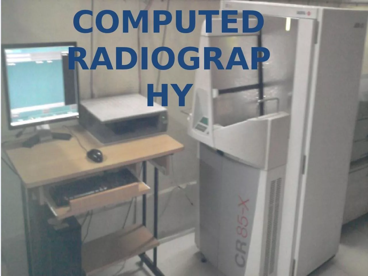
1. COMPUTED RADIOGRAPHY
2. Computed Radiography (CR)Imaging system comprised of:Photostimulable Storage Phosphor-to acquire the x-ray projection imageCR Reader-to extract the electronic latent imageDigital electronics-to convert the signals to digital form
3. In CR , in place of a film to create the image , an imaging plate (IP) made of photostimulable phosphor is used. Hence, instead of developing film in darkroom, the imaging plate is run through a special laser scanner, or CR reader, that reads the image. The digital image can then be viewed and enhanced using software
4. LUMINESCENCE is emission of light by a substance. Types:FLORESCENCEPHOSPHORSCENCE CR is based on the principle of PHOSPHORSCENCE which is is emission of light that is delayed for 10-8 seconds or more.INTENSIFYING SCREENS are based on the principle of FLORESCENCE which is emission of light immediately within 10-8 seconds of exposure.PRINCIPLE
5. The phosphor that is currently used is composed of BARIUM FLUOROHALIDE DOPED WITH EUROPIUM.Halide = BROMIDE (85 %) + IODIDE (15 %) EUROPIUM -as impurity or activator. It creates positive energy traps where electrons can bind on excitation.PHOSPHOR IN CR
6. Phosphor powdered form - mixed with a binder or adhesive material - laid down as a base with a thickness of about 0.3mm.The plate is inserted into a light tight cassette, mostly made of fibre.
7.
8.
9.
10. 12 cassettes can be read at a time.Cassettes / plates available in different sizes:Size is written on cassette-- 43 x 35 cm - 35 x 35 cm- 10 x 12 inches- 8 x 10 inchesCASSETTES
11. Single cassette : 30,000 X-rays in lifetime.Latent image is saved in the screen.Lead- on backside of screen- prevents scattering of X-rays.
12. Cost of large cassette – around 41,000.Plate – ideally cleaned after every 15 daysWith solution containing ethanolWith cellulose clothShould be prevented from scratches for better life.
13.
14. In CR, the radiographic exposure is made using conventional x ray equipment. STEPS OF CR IMAGING
15.
16.
17.
18.
19. The two lights are of different wavelength is critical for image retrieval. Filter is used which absorbs the red light and allows the green light to pass through. -An OPTICAL FIBRE is used to direct the light to the PHOTOMULTIPLIER TUBE. -It converts the light signal into ELECTRIC SIGNAL. -The entire plate can be scanned by moving the image plate perpendicular to the scan line of the laser beam.
20. The output of photomultiplier tube is in the form of ELECTRIC ANALOG SIGNAL corresponding to absorbed x rays.signal from photomultiplier tube is then amplified converted to a digital signal stored in a computer by means of a ANALOGE TO DIGITAL CONVERTER.
21.
22. Following the read cycle the residual signal from the plate is erased by exposing it to a bright light source- high intensity Na discharge lamps.The time for a CR reader to extract the image from the plate is generally between about 30 and 45s.
23.
24.
25.
26.
27. CR IN OUR SETUPAGFA CR 85- X - BELGIUMSTORAGE CAPACITY AVR. -1500 IMAGES / 160 GBConnected through-SCANDOC- 4 computers in departmentAPACS - Hospital network
28. - Cost around 18 LAKH.- 12 CASSETTES READ AT A TIMECR IN OUR SETUP-Provided with printer- DRYSTAR 5302
29.
30.
31.
32.
33.
34.
35. CONCEPTS IN DIGITAL IMAGINGDYNAMIC RANGEPIXELSPATIAL RESOUTIONCONTRAST RESOLUTIONIMAGE NOISE
36. The dynamic range of CR is better compared to the film.The dynamic range forCR=10000:1CONVENTIONAL=100:1 DYNAMIC RANGEThe dynamic range is graph of light emitted from the plate to dose of x rays produced.
37. The dynamic range of CR is linear. - It will accept wider range of exposure Dynamic range of conventional is S shaped. - Low exposure and high exposure will lead to insufficient image quality and failed exposure.Range of doses that can be imaged in CR/ DR is much greater than for conventional.
38.
39. Due to wider dynamic range of CR, PSP should be read in 2 steps using PREREADING:Small portion of image scanned by laser beamData analysed to compare exposure level of imageSensitivity of photomultiplier tube is adjusted to that exposure levelAllows examination made with wide range of mAs settings to be converted to diagnostically imp image
40. Smallest complete sample of an image – expressed as binary codes ( bits ).Smaller the size of pixel- Better resolution.pixelIn digital imaging each image is divided into a matrix of individual cells called as PIXELS .
41. Minimum resolvable separation between high contrast subjects.Ability to detect fine detail. FACTORS LIMITING SPATIAL RESOLUTIONPixel size-Scattering of laser beam in the phosphor layerDiameter of scanning laser beam Size of phosphor grains Spatial resolution
42. The spatial resolution with CR IS LESS than with conventional radiography as in depends on pixel size and OBJECTS SMALLER THAN PIXEL CANNOT BE READ.
43. It is colour / grey scale differentiation.It indicates the number of shades of grey that a detector can capture.Ability to distinguish between adjacent areas in an image.Depends on properties of tissues & method of image formation.CONTRAST RESOLUTION
44. All images have unwanted fluctuations that are unrelated to object being imaged.It may be due to: X-ray quantum noiseNoise due to imaging systemIndirect DR system- conversion to lightImage noise
45. DIGITAL IMAGE PROCESSINGADJUST & OPTIMIZE CONTRAST Look up table processing WindowingREDUCE IMAGE NOISEINCREASE VISIBILITY OF DETAILEDGE ENHANCEMENT
46. DIGITAL IMAGE PROCESSINGADJUST & OPTIMIZE CONTRAST Look up table processing WindowingREDUCE IMAGE NOISEINCREASE VISIBILITY OF DETAILEDGE ENHANCEMENT
47.
48. LUT PROCESSINGLook up tables (LUTs) are data stored in computer that is used to substitute new values for each pixel during processing.
49. Process of selecting some segment of total pixel value range and then displaying the pixel values within that segment over full brightness. Contrast will be visible only for the pixel values that are within the selected window. All pixel values that are either below or above the window will be all white or all black and display no contrast. windowing
50. To display and enhance the contrast in selected segments of the total pixel value range.When the window is set to cover the lower segment of total pixel value range, we see good contrast in the lighter areas like the medistimum. Setting the window to the higher segment produces good contrast in the darker areas like the lungs. windowing
51.
52. DIGITAL IMAGE PROCESSINGADJUST & OPTIMIZE CONTRAST Look up table processing WindowingREDUCE IMAGE NOISEINCREASE VISIBILITY OF DETAILEDGE ENHANCEMENT
53. All images have unwanted fluctuations in the levels of grey in the image that are unrelated to object being imaged.Limits the ability to see the low contrast fine detail of an image.Noise reduces as the number of photons increases.Image noise
54. It may be due to:X-ray quantum noise- QUANTUM MOTTLENoise due to imaging systemIndirect DR system- conversion to lightX-ray scatterVeiling glare
55. It is the statistical fluctuations in the number of photons that exit the patient. Generated because of very low signal levels being detected to produce the image.Lower the number of photons detected- greater the variation in signal. Limiting factor in all x ray imaging.Causes fluctuations in brightness or density of image.Quantum mottle
56. 1]It reduces radiographic contrast.2]It causes small structures with equal attenuation to have different contrast depending on whether they are present on thick or thin part. It nullifies even the log conversion.3]It raises the patient dose required to obtain a given x ray photon statistical confidence level.X-RAY GRID & PRIMARY BEAM MAGNIFICATION REDUCE SCATTERX ray scatter
57. Light that is scattered and reflected by lens system. The image intensifier and TV system contribute to it.It has same effect on image as x ray scatter.Important in CCD type of detectors in DR system.VEILING GLARE
58. Noise reduced by low pass filtering. Pixels are averaged with closest neighbouring pixelsLow contrast objects are better appreciated BUT…Compromises some resolution… small details & edges are blurred.NOISE SMOOTHENING
59. It is a method to reduce noise by adding together several frames.It reduces both electronic and quantum noise. Frame integration;
60. DIGITAL IMAGE PROCESSINGADJUST & OPTIMIZE CONTRAST Look up table processing WindowingREDUCE IMAGE NOISEINCREASE VISIBILITY OF DETAILEDGE ENHANCEMENT
61. To increase visibility of small structures with moderate to high contrast.To detect finer detail of an image.Subtraction of low pass filtered image( info about large structures and low noise) from original yields image in which edges and small structures remain.EDGE ENHANCEMENT
62. It exaggerates the contrast at boundary between structures. Makes structures more easily visible. Fine details enhanced BUT…. Noise is increased.
63.
64.
65. DIGITAL IMAGE PROCESSING
66. No silver based film or chemicals.Saves time and effortsReduced film storage costs because images stored digitally.Reprinting possibleReusable phosphor platesFewer retakes due to under- or over-exposure which results in lower overall dose to the patient.Advantages of CR
67. Option to change-Contrast-Brightness-Image rotation, flip , inversion-Image crop-Image label-Bone & soft tissue window-Count distance & angles Used with PACSImage acquisition is much faster - image previews available < 15 seconds.
68.
69. Resultant lower spatial resolution as compared to film images.To keep the same SNR, CR needs 20% more radiation exposure as CR is medium speed film. DISADVANTAGESImaging plates (IPs) are expensive and can be damaged if the system being used requires manual handling of the IPs.
70. TO SUMMARIZE PHOTOSTIMULABLE PHOSPHOR PLATE Exposed to X-rays Electrons in europium traps- LATENT IMAGE On exposure to laser light – emit light with higher energy Directed to photomultiplier tube converted to electrical signal & amplified
71. Converted to digital signal Stored in computerImage is divided into matrix of individual cells— PIXELS Value stored in each pixel in binary formatImage is processed to :Optimize contrast , reduce image noise , edge enhancement
72. CR :Saves time, efforts.Better quality images.Post- exposure image processing.Storage facility.BUT--- LESS SPATIAL RESOLUTION.
73.
74. Thank you