
SSelfprimingsegmental type with verly lowNPSHCEHSizes1201 6108 12025 61085 12027 61077PUMPTECHNOLOGYCEH133513016001E052015Technical dataCapacitymax 35 mhDelivery headmax 354mSpeedmax 1800 1 ID: 861729
Download Pdf The PPT/PDF document "ide Channel Pumps" is the property of its rightful owner. Permission is granted to download and print the materials on this web site for personal, non-commercial use only, and to display it on your personal computer provided you do not modify the materials and that you retain all copyright notices contained in the materials. By downloading content from our website, you accept the terms of this agreement.


1 S ide Channel Pumps S el f - priming ,
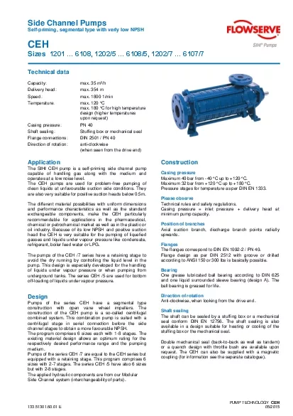
S ide Channel Pumps S el f - priming , segmental type with verly low NPSH CEH Sizes 1201 ⦠6108, 1202/5 ⦠6108/5, 1202/7 ⦠6107/7 PUMP TECHN OLOGY CEH 133. 51301 . 60 .01 E 0 5 /201 5 T echnical data Capacity : max. 3 5 m³/h Delivery head : max. 3 54 m Speed : max. 1800 1/min Temperatur e : max. 120 °C max. 180 °C f or high temperatur e design (h igher t emperature s upon request ) Casing pressure : PN 40 Shaft sealing : St uffing box or me chanical seal Flange connections : DIN 2501 / PN 40 D irection of rotation : anti - clockwise (when seen from the drive end) A pplication The SIHI CEH pump is a self - priming side channel pump capable of handling gas along with the medium and operates at a l ow noise level. The CEH pumps are used for problem - free pumping of clean liquids at unfavourable suction side conditions. They are also very suitable for positive suction heads below 0.5m. The different material possibilities with uniform dimensions and p erformance characteristics as well as the standard exchangeable components, make the CEH particularly chemical or petrochemical market as well as in the plastic or oil industry. Because of its low NPSH and positive suction head the CEH is very suitable for the pumping of liquefied gasses and liquids under vapour pressure like condensate, refrigerant, boiler feed water or LPG. The pumps of the CEH /7 series have a retaining stage to avoid the dry running by controlling the liquid level in the pump. This design is especially developed for the handling of liquids under vapour pressure or when pumping from underground tanks. The series CEH /5 are used for bottom off - loading of liquids under vapour pressure. Design construction with open vane wheel impellers. The construction of the CEH pump is a so - called centrifugal combined system. This combination pump is suited with a centrifugal stage in serial connect
2 ion b efore the side channel stages to
ion b efore the side channel stages to obtain a more favourable NPSH. The program comprises 6 sizes each with 1 - 8 stages. The existing material design allows an optimum rating for the respectively desired performance range and the pumping medium. Pumps of the se ries CEH /7 are equal to the CEH series but equipped with a retaining stage. This program comprises 6 sizes with 2 - 7 stages. The series CEH /5 have also 6 sizes but with 2 - 8 stages. Side Channel system (interchangeability of parts) . Construction Casing pressure Maximum 40 bar from - 40 °C up to +120 °C. Maximum 32 bar from +120 °C up to +180 °C. Pressure stages for temperature as per DIN EN 1333 . Please observe Technical rules and safety regulation s. Casing pressure = inlet pressure + delivery head at minimum pump capacity. Position of branches Axial suction branch, discharge branch points radially upwards. Flan ges The flanges correspond to DIN EN 1092 - 2 / PN 40. Flange design as per DIN 2512 with groove or drilled according to ANSI 150 or 300 lbs is basically possible. B earing One grease lubricated ball bearing according to DIN 625 an d one liquid surrounded sleeve bearing (design A). The ball bearing is greased for life . D irection of rotation Anti - clockwise, when looking from the drive end . S haft sealing seal conform DIN EN 12756. The shaft sealing is also available in a design suitable for heating or cooling of the stuffing box or the mechanical seal. Double mechanical seal (back - to - back as well as tandem) or a quench design with throttle bush are available upon request. The CEH can also be supplied with a magnetic c oupling (for information see the separate catalogue). CEH 2 M aterial design C ast iron and ductile iron Pos. C omponents M aterial design 0A 0B 0F 1A 1B 1F 1060 S uction casing E N - GJL - 250 EN - GJS - 400 - 18 - LT 1070 D ischarge casing E N - GJL - 250 EN
3 - GJS - 400 - 18 - LT 1080 1090 1
- GJS - 400 - 18 - LT 1080 1090 1140 1141 I nterm ediate piece EN - GJL - 250 EN - GJS - 400 - 18 - LT 2100 Shaft X 20 Cr 13 2310 Impeller E N - GJL - 250 2350 V ane wheel impeller CuZn40Al2 G - X 3 CrNiMoCuN 26 6 3 3 PAEK CuZn40Al2 G - X 3 CrNiMoCuN 26 6 3 3 PAEK 3500 B e aring housing EN - GJL - 250 4410 M echanical seal casing EN - GJL - 250 EN - GJS - 400 - 18 - LT 4510 Stuffing box casing E N - GJL - 250 EN - GJS - 400 - 18 - LT 0241 B earing bush CY 10 C / C arbon Antimony * * B earing bush in carbon antimony is used only in the high temperature design. This high temperature design is also provided with cup springs and a cooled stuffing box or cooled mechanical seal. S tainless steel Pos. C omponents M aterial design 4B 4F 1060 S uction casing G - X 6 CrNiMo 18 10 1070 D ischarge casing G - X 6 CrNiMo 18 10 1080 1090 1140 1141 I nterm ediate piece G - X 6 CrNiMo 18 10 2100 Shaft X 5 CrNiMo 17 12 2 2310 Impeller G - X 3 CrNiMoNb 18 10 2350 V ane wheel impeller G - X 3 CrNiMoCuN 26 6 3 3 PAEK 3500 B e aring housing EN - GJL - 250 c oated 4410 M echanical seal casing G - X 6 CrNiMo 18 10 0241 B earing bush CY 10 C / C arbon Antimony * * B earing bush in carbon antimony is used only in the high temperature design. This high temperature design is also provided with cup springs and a cooled stuffing box or cooled mechanical seal . C asing seal T he casing seal can be sealed with a liquid compound or soft Teflon . D rive B y lelectrica motor, type of construction IM B3 . F or LPG, EExe or E e x d ( e) motors are available . CEH 3 S ectional drawing and part s list C EH with stuffing box C EH with mechanical seal U nbalanced as well as balanced mechanical seals are available . CEH /7 w ith retaining stage 0241 B earing bush 1060 S uction casi
4 ng 1070 D ischarge casing 1080 I
ng 1070 D ischarge casing 1080 Intermediate piece 1081 R etaining stage 1090 S uction i ntermediate piece 1140 Discharge i ntermediate piece 1141 Discharge i ntermediate piece 2100 Shaft 2310 Impeller 2350 Vane wheel impeller 3500 Bearing housing 4330 Mechanical seal 4410 Mechanical seal casin g 4420 Cooling insert 4510 St uffing box casing 4610 St uffing box C ooled stuffing box C ooled mechanical seal CEH 4 P erformance range G eneral conditions Liquid : Wa t er D ensity : 1 kg/dm ³ Vis c osit y : 1 cSt Temperatur e : 20 °C Atmosph eric pressure : 1013 mbar Characteristic t oleran ces C apacity ± 5 % - Delivery head ± 5 % - Power + 10% F or designs with a mechanical seal or a casing seal of soft Teflon, the tolerance for the delivery head is extended by 2% each . Me asuring standard According to ISO 5198 . = Maximum f or CEH /7 ( with retaining stage ) = Minimum f or CEH /5 ( e . g . LPG handling ), CEH/7 T he NPSH cur ve is suitable for liquids without gas. When using a liquid containing das (e.g. water 20° C) a safety margin of 1 m has to added . n = 1450 1/min CEH 5 D imension chart, pump set drawing and performance curves C E H 1 2 00 a nd CEH 1200/5 V alues are valid for water at 1 k g/dm³ a nd Vis c osit y at 1 cSt . C apacity ± 5 % - Delivery head ± 5 % - Power + 10% F or designs with a mechanical seal or a casing seal of soft Teflon, the tolerance for the delivery head is extended by 2% each . P ump Motor B ase C oupling W eight [kg] D imensions [mm] size kW kW 2) s ize plat e B BDS 2) Pum p set a b2 c d e1 e2 v f1 h3 m1 m2 w* w1 1201 0 . 37 1 ) 71 P007 68 1) 18 39 195 317 20 15 350 285 110 - 9 135 238 204 609 570 0 . 55 80 P008 45 297 400
5 265 120 140 643 640 120 2 0
265 120 140 643 640 120 2 0 . 55 0 . 55 8 0 P008 68 76 20 47 229 297 20 15 400 265 120 - 9 140 272 238 677 640 0 . 75 0 . 75 8 0 44 1 . 1 1 . 0 9 0S P241 56 330 25 19 480 290 125 165 735 730 1203 0 . 75 0 . 75 8 0 P210 68 76 22 52 263 300 25 19 420 260 115 - 9 165 306 272 711 650 1 . 1 1 . 0 9 0S P241 58 330 480 290 125 769 730 1 . 5 1 . 35 9 0L 62 1204 1 . 1 1 . 0 9 0S P241 68 76 24 60 297 330 25 19 480 290 125 - 9 165 340 306 803 730 1 . 5 1 . 35 9 0L 64 2 . 2 2 . 0 1 00L P272 80 88 75 360 5 40 320 140 844 820 1205 1 . 1 1 . 0 9 0S P272 68 76 26 66 331 360 25 19 540 320 140 - 9 165 374 340 837 820 1 . 5 1 . 35 9 0L 70 2 . 2 2 . 0 1 00L 80 88 77 878 1206 1 . 5 1 . 35 9 0L P272 68 76 28 72 365 360 25 19 540 320 140 - 9 165 408 374 871 820 2 . 2 2 . 0 1 00L P015 80 88 84 361 15 600 325 160 150 912 920 3 . 0 2 . 5 1 00L 85 1207 1 . 5 1 . 35 9 0L P015 68 76 30 74 399 361 25 15 600 325 160 - 9 150 442 408 905 920 2 . 2 2 . 0 1 00L 80 88 86 946 3 . 0 2 . 5 1 00L 87 1208 2 . 2 2 . 0 1 00L P015 80 88 32 88 433 361 25 15 600 325 160 - 9 150 476 442 980 920 3 . 0 2 . 5 1 00L 89 * D imensions depend upon the motor brand . 1) Not for design CEH /5, 2) for EExe II T3 m otor s , 3) A safety margin of 1 m has to be added when using a liquid containing gas . The weight for stainless ste el will be approximately 6% higher. n = 1450 1/min CEH 6 D imension chart, pump set drawing and performance curves C EH 3100 a nd CEH 3100/5 V alues are valid for water at 1 k g/dm³ a nd Vis c osi
6 t y at 1 cSt . C apacity ± 5
t y at 1 cSt . C apacity ± 5 % - Delivery head ± 5 % - Power + 10% F or designs with a mechanical seal or a casing seal of soft Teflon, the tolerance for the delivery head is extended by 2% each . P ump Motor B ase C oupling W eight [kg] D imensions [mm] size k W kW 2) s ize plat e B BDS 2) Pum p S et a b2 c d e1 e2 v f1 h3 m1 m2 w* w1 3101 0. 75 1) 80 P008 68 1) 31 60 213 297 20 15 400 265 120 - 13 152 261 227 691 640 1 . 1 90S P241 67 330 25 19 480 290 125 177 749 730 3102 1 . 1 1 . 0 9 0S P241 68 78 34 72 253 330 25 19 480 290 125 - 13 177 301 267 789 730 1 . 5 1 . 35 9 0L 74 2 . 2 2 . 0 1 00L P272 80 88 81 360 540 320 140 830 820 3103 2 . 2 2 . 0 1 00L P272 80 88 38 89 293 360 25 19 540 320 140 - 13 177 341 307 870 820 3 . 0 2 . 5 1 00L 90 3104 2 . 2 2 . 0 1 00L P272 80 88 42 93 333 360 25 19 540 320 140 - 13 177 381 347 910 820 3 . 0 2 . 5 1 00L 94 4 . 0 3 . 6 1 12M P015 117 361 15 600 325 160 162 931 920 3105 3 . 0 2 . 5 1 00L P015 80 88 45 102 373 361 25 15 600 325 160 - 13 162 421 387 950 920 4 . 0 3 . 6 1 12M 120 971 5 . 5 5 . 0 1 32S P017 95 103 158 700 200 192 1047 1100 3106 4 . 0 3 . 6 1 12M P015 80 88 48 123 413 361 25 15 600 325 160 - 13 162 461 427 1011 920 5 . 5 5 . 0 1 32S P017 95 103 161 700 200 192 1087 1100 7 . 5 6 . 8 1 32M 171 1113 3107 4 . 0 3 . 6 1 12M P017 80 88 52 143 453 361 25 15 700 325 200 - 13 172 501 467 1051 1100 5 . 5 5 . 0 1 32S 95 103 165 192 1127 7 . 5 6 . 8 1 32M 205 1153 3108 5 . 5 5 . 0 1
7 32S P017 95 1 03 55 198 493
32S P017 95 1 03 55 198 493 361 25 15 700 325 200 - 13 192 541 507 1167 1100 7 . 5 6 . 8 1 32M 208 1193 11 . 0 10 . 0 1 60M P436 253 540 30 24 840 490 215 240 1285 1270 * D imensions depend upon the motor brand . 1) Not for design CEH /5, 2) for EExe II T3 m otor s , 3) A safety margin of 1 m has to be added when using a liquid containing gas . The weight for stainless ste el will be approximately 6% higher. n = 1450 1/min CEH 7 D imension chart, pump set drawing and performance curves CEH 3600 a nd CEH 3600/5 V alues are valid for water at 1 k g/dm³ a nd Vis c osit y at 1 cSt . C apacity ± 5 % - Delivery head ± 5 % - Power + 10% F or designs with a mechanical seal or a casing seal of soft Teflon, the tolerance for the delivery head is extended by 2% each . P ump M otor B ase C oupling W eight [kg] D imensions [mm] size kW kW 2) s ize plat e B BDS 2) Pum p Set a b2 c d e1 e2 v f1 h3 m1 m2 w* w1 3601 0 . 75 1 ) 80 P008 68 1) 31 55 213 297 20 15 400 265 120 - 13 152 261 227 691 640 1 . 1 90S P241 67 330 25 19 480 290 125 177 749 730 1 . 5 90L 74 3602 1 . 5 1 . 35 9 0L P241 68 76 34 74 253 330 25 19 480 290 125 - 13 177 301 267 789 730 2 . 2 2 . 0 1 00L P272 80 88 89 360 540 320 140 830 820 3603 2 . 2 2 . 0 1 00L P272 80 88 38 89 293 360 25 19 540 320 140 - 13 177 341 307 870 820 3 . 0 2 . 5 1 00L 101 4 . 0 3 . 6 1 12M 119 891 3604 3 . 0 2 . 5 1 00L P272 80 88 42 105 333 360 25 19 540 320 140 - 13 177 381 347 910 820 4 . 0 3 . 6 1 12M P015 117 361 15 600 325 160 162 931 920 5 . 5 5 . 0 1 32S 95 103 152 1 82 1007 3
8 6 05 3 . 0 2 . 5 1 00L P015 8
6 05 3 . 0 2 . 5 1 00L P015 80 88 45 102 373 361 25 15 600 325 160 - 13 162 421 387 950 920 4 . 0 3 . 6 1 12M 120 971 5 . 5 5 . 0 1 32S P017 95 103 171 700 200 192 1047 1100 3 6 06 4 . 0 3 . 6 1 12M P015 80 88 48 123 413 361 25 15 600 32 5 160 - 13 162 461 427 1011 920 5 . 5 5 . 0 1 32S P017 95 103 161 700 200 192 1087 1100 7 . 5 6 . 8 1 32M 171 1113 3607 5 . 5 5 . 0 1 32S P017 95 103 52 165 453 361 25 15 700 325 200 - 13 192 501 467 1127 1100 7 . 5 6 . 8 1 32M 168 1153 3 6 08 5 . 5 5 . 0 1 32S P017 95 103 55 161 493 361 25 15 700 325 200 - 13 192 541 507 1167 1100 7 . 5 6 . 8 1 32M 171 1193 11 . 0 10 . 0 1 60M P436 254 540 30 24 840 490 215 240 1285 1270 * D imensions depend upon the motor brand . 1) Not for design CEH /5, 2) for EExe II T3 m otor s , 3) A safety margin of 1 m has to be added when using a liquid containing gas . The weight for stainless ste el will be approximately 6% higher. n = 1450 1/min CEH 8 D imension chart, pump set drawing and performance curves CEH 4100 a nd CEH 4100/5 V alues are valid for water at 1 k g/dm³ a nd Vis c osit y at 1 cSt . C apacity ± 5 % - Delivery head ± 5 % - Power + 10% F or designs with a mechanical seal or a casing seal of soft Teflon, the tolerance for the delivery head is extended by 2% each . P ump M otor B ase C oupling W eight [kg] D imensions [mm] size kW kW 2) s ize plat e B BDS 2) Pum p Set a b2 c d e1 e2 v f1 h3 m1 m2 w* w1 4101 1 . 5 1 ) 90L P241 68 1) 41 81 268 330 25 19 480 290 125 - 23 197 294 260 798 730 2 . 2 100L P272 80 95 360 540 320 140 839 820 4102 2 . 2
9 2 . 0 1 00L P272 80 88 47
2 . 0 1 00L P272 80 88 47 98 323 360 25 19 540 320 140 - 23 197 349 315 894 820 3 . 0 2 . 5 1 00L 110 4 . 0 3 . 6 1 12M 128 915 4103 4 . 0 3 . 6 1 12M P015 80 88 53 128 378 361 25 15 600 325 160 - 23 182 404 370 970 920 5 . 5 5 . 0 1 32S P017 95 179 700 200 192 1046 1100 4104 5 . 5 5 . 0 1 32S P017 95 103 59 172 433 361 25 15 700 325 200 - 23 192 459 425 1101 1100 7 . 5 6 . 8 1 32M 182 1127 4105 5 . 5 5 . 0 1 32S P017 95 103 65 178 488 361 25 15 700 32 5 200 - 23 192 514 480 1156 1100 7 . 5 6 . 8 1 32M 181 1182 11 . 0 10 . 0 1 60M P385 264 490 30 24 740 440 240 1274 1140 4106 7 . 5 6 . 8 1 32M P385 95 103 70 196 543 490 30 24 740 440 200 - 23 212 569 535 1237 1140 11 . 0 10 . 0 1 60M P436 269 540 840 490 215 240 1329 1270 4107 7 . 5 6 . 8 1 32M P436 95 103 76 202 598 540 30 24 840 490 215 - 23 212 624 590 1292 1270 11 . 0 10 . 0 1 60M 275 240 1384 15 . 0 13 . 5 1 60L P487 110 118 349 610 35 28 940 550 240 260 1446 1420 4108 11 . 0 10 . 0 1 60M P487 95 103 82 281 653 610 35 28 940 550 240 - 23 260 679 645 1439 1420 15 . 0 13 . 5 1 60L 110 118 355 1501 * D imensions depend upon the motor brand . 1) Not for design CEH /5, 2) for EExe II T3 m otor s , 3) A safety margin of 1 m has to be added when using a liquid containing gas . The weight for stainless ste el will be approximately 6% higher. n = 1450 1/min CEH 9 D imension chart, pump set drawing and performance curves CEH 5100 a nd CEH 5100/5 V alues are valid for water at 1 k g/dm³ a nd Vis c osit y at 1 cSt . C apacity ± 5 % - Deliver
10 y head ± 5 % - Power + 10% F o
y head ± 5 % - Power + 10% F or designs with a mechanical seal or a casing seal of soft Teflon, the tolerance for the delivery head is extended by 2% each . P ump Motor B ase C oupling W eight [kg] D imensions [mm] size kW kW 2) s ize pl a te B BDS 2) Pum p Set a b2 c d e1 e2 v f1 h3 m1 m2 w* w1 5101 3 . 0 1 ) 100L P272 80 1) 60 123 305 360 25 19 540 320 140 - 28 225 353 315 918 820 4 . 0 112M P015 162 361 15 600 325 160 210 939 920 5 . 5 132S 95 170 1015 5102 5 . 5 5 . 0 1 32S P017 95 103 70 183 380 361 25 15 700 325 200 - 28 220 428 390 1090 1100 7 . 5 6 . 8 1 32M 193 1116 11 . 0 10 . 0 1 60M P385 269 490 30 24 740 440 240 1208 1140 5103 7 . 5 6 . 8 1 32M P017 95 103 80 196 455 361 25 15 700 325 200 - 28 220 503 465 1191 1100 11 . 0 10 . 0 1 60M P385 279 490 30 24 740 440 240 1283 1140 15 . 0 13 . 5 1 60L P436 110 118 353 540 840 490 215 1345 1270 5104 11 . 0 10 . 0 1 60M P436 95 103 90 289 530 540 30 24 840 490 215 - 28 240 578 540 1358 1270 15 . 0 13 . 5 1 60L 110 118 363 1420 5105 15 . 0 13 . 5 1 60L P487 110 118 101 374 605 610 35 28 940 550 240 - 28 260 653 615 1495 1420 18 . 5 15 . 0 1 80M 395 280 1557 22 . 0 17 . 5 1 80L 125 135 415 5106 15 . 0 13 . 5 1 60L P487 110 118 111 384 680 610 35 28 940 550 240 - 28 260 728 690 1570 1420 18 . 5 15 . 0 1 80M P538 423 660 1060 600 280 280 1632 1620 22 . 0 17 . 0 1 80L 125 135 425 30 . 0 24 . 0 2 00L 506 300 1690 5107 18 . 5 15 . 0 1 80M P538 110 118 121 415 75 5 660 35 28 1060 600 280 - 28 280 8
11 03 765 1707 1620 22 . 0 17 . 5
03 765 1707 1620 22 . 0 17 . 5 1 80L 125 135 435 30 . 0 24 . 0 2 00L 516 300 1765 5108 22 . 0 17 . 5 1 80L P539 125 135 132 446 830 660 35 28 1060 600 280 - 28 280 878 840 1782 1620 30 . 0 24 . 0 2 00L S§() 527 540 40 1200 490 300 300 1840 1800 * D imensions depend upon the motor brand . 1) Not for design CEH /5, 2) for EExe II T3 m otor s , 3) A safety margin of 1 m has to be added when using a liquid containing gas . The weight for stainless ste el will be approximately 6% higher. n = 1450 1/min CEH 10 D imension chart, pump set drawing and performance curves CEH 6100 a nd CEH 6100/5 V alues are valid for water at 1 k g/dm³ a nd Vis c osit y at 1 cSt . C apacity ± 5 % - Delivery head ± 5 % - Power + 10% F or designs with a mechanical seal or a casing seal of soft Teflon, the tolerance for the delivery head is extended by 2% each . P ump Motor B ase C oupling W eight [kg] D imensions [mm] size kW kW 2) s ize plat e B BDS 2) Pum p Set a b2 c d e1 e2 v f1 h3 m1 m2 w* w1 6101 5 . 5 1 ) 132S P017 95 1 ) 80 206 338 361 25 15 700 325 200 - 35 240 391 353 1073 1100 7 . 5 132M 203 1099 6102 11 . 0 10 . 0 1 60M P385 95 103 92 291 428 490 30 24 740 440 200 - 35 260 481 443 1281 1140 15 . 0 13 . 5 1 60L P436 110 118 365 540 840 490 215 1343 127 0 6103 18 . 5 15 . 0 1 80M P487 110 118 105 404 518 610 35 28 940 550 240 - 35 280 571 533 1495 1420 22 . 0 17 . 5 1 80L 125 135 419 6104 22 . 0 17 . 5 1 80L P487 125 135 117 431 608 610 35 28 940 550 240 - 35 280 661 623 1585 1420 30 . 0 24 . 0 2 00L P538 512 660 1060 600 280 300 1643 1620 6105 30 .
12 0 24 . 0 2 00L P538 125 135
0 24 . 0 2 00L P538 125 135 130 525 698 660 35 28 1060 600 280 - 35 300 751 713 1733 1620 37 . 0 30 . 0 2 25S 140 152 594 325 1798 6106 30 . 0 24 . 0 2 00L P538 125 135 142 537 788 660 35 28 1060 600 2 80 - 35 300 841 803 1823 1620 37 . 0 30 . 0 2 25S S609 140 152 606 730 40 1200 670 310 325 1888 1820 45 . 0 36 . 0 2 25M 670 6107 30 . 0 24 . 0 2 00L S389 125 135 155 550 878 540 40 28 1200 490 300 - 35 300 931 893 1913 1800 37 . 0 30 . 0 2 25S S60 9 140 152 619 730 670 310 325 1978 1820 45 . 0 36 . 0 2 25M 683 6108 37 . 0 30 . 0 2 25S 14211 140 152 167 532 968 740 40 28 1300 690 350 - 35 345 1021 983 2003 2000 45 . 0 36 . 0 2 25M 630 2080 55 . 0 44 . 0 2 50M 14212 160 - 7 01 400 370 2125 2100 * D imensions depend upon the motor brand . 1) Not for design CEH /5, 2) for EExe II T3 m otor s , 3) A safety margin of 1 m has to b e added when using a liquid containing gas . The weight for stainless ste el will be approximately 6% higher. n = 1450 1/min CEH 11 D imension chart, pump set drawing and performance curves CEH 1200/7 ( w ith retaining stage ) V alues are valid for water at 1 k g/dm³ a nd Vis c osit y at 1 cSt . C apacity ± 5 % - Delivery head ± 5 % - Power + 10% F or designs with a mechanical seal or a casing seal of soft Teflon, the tolerance for the delivery head is extended by 2% each . P ump Motor B ase C oupling W eight [kg] D imensions [mm] size kW s ize Größe plat e B DS Pump Set a b2 c d e1 e2 v f1 h3 m1 m2 w* w1 1202/7 0 . 55 8 0 P210 76 22 52 263 300 25 19 420 260 115 - 9 165 306 272 709 650 0 . 75 8 0 53 1203/7 0 . 75 8 0
13 P241 76 24 54 297 330 25
P241 76 24 54 297 330 25 19 480 290 125 - 9 165 340 306 743 730 1 . 1 9 0S 64 796 1204/7 1 . 1 9 0S P272 76 26 70 331 360 25 19 540 320 140 - 9 165 374 340 930 820 1 . 5 9 0L 71 1205/7 1 . 5 9 0L P272 76 28 73 365 360 25 19 540 320 140 - 9 165 408 374 864 820 2 . 0 1 00L P015 88 84 361 15 600 325 160 150 922 1206/7 1 . 5 9 0L P015 76 30 69 399 361 25 15 600 325 160 - 9 150 442 408 898 920 2 . 0 1 00 L 88 86 956 1207/7 1 . 5 9 0L P015 76 32 71 433 361 25 15 600 325 160 - 9 150 476 442 932 920 2 . 0 1 00L 88 91 990 * D imensions depend upon the motor brand 1) A safety margin of 1 m has to be added when using a liquid containing gas . n = 1450 1/min CEH 12 D imension chart, pump set drawing and performance curves CEH 3100/7 ( with retaining stage ) V alues are valid for water at 1 k g/dm³ a nd Vis c osit y at 1 cSt . C apacity ± 5 % - Delivery head ± 5 % - Power + 10% F or designs with a mechanical seal or a casing seal of soft Teflon, the tolerance for the delivery head is extended by 2% each . P ump Motor B ase C oupling W eight [kg] D imensions [mm] size k W s ize Größe plat e B DS Pump Set a b2 c d e1 e2 v f1 h3 m1 m2 w* w1 3102/7 1 . 5 9 0L P272 76 38 8 7 293 360 25 19 540 320 140 - 13 177 341 307 822 820 2 . 0 1 00L 88 100 880 3103/7 2 . 0 1 00L P272 88 42 104 333 360 25 19 540 320 140 - 13 177 381 347 920 820 2 . 5 1 00L 106 3104/7 2 . 5 1 00L P015 88 45 101 373 361 25 15 600 325 1 60 - 13 162 421 387 960 920 3 . 6 1 12M 107 966 3105/7 2 . 5 1 00L P015 88 48 107 413 361 25 15
14 600 325 160 - 13 162 461 42
600 325 160 - 13 162 461 427 1000 920 3 . 6 1 12M 110 1006 3106/7 3 . 6 1 12M P017 88 52 117 453 361 25 15 700 325 200 - 13 172 501 467 104 6 1100 5 . 0 1 32S 103 151 192 1142 3107/7 3 . 6 1 12M P017 88 55 120 493 361 25 15 700 325 200 - 13 172 541 507 1086 1100 5 . 0 1 32S 103 154 192 1182 * D imensions depend upon the motor brand 1) A safety margin of 1 m has to be added when using a liquid containing gas . n = 1450 1/min CEH 13 D imension chart, pump set drawing and performance curves CEH 3600/7 ( with retaining stage ) V alues are valid for water at 1 k g/dm³ a nd Vis c osit y at 1 cSt . C apacity ± 5 % - Delivery head ± 5 % - Power + 10% F or designs with a mechanical seal or a casing seal of soft Teflon, the tolerance for the delivery head is extended by 2% each . P ump Motor B as e C oupling W eight [kg] D imensions [mm] size kW s ize Größe p la te B DS Pump Set a b2 c d e1 e2 v f1 h3 m1 m2 w * w1 3602/7 1 . 5 9 0L P272 76 38 87 293 360 25 19 540 320 140 - 13 177 341 307 822 820 2 . 0 1 00L 88 100 880 3603/7 2 . 0 1 00L P272 88 42 104 333 360 25 19 540 320 140 - 13 177 381 347 920 820 2 . 5 1 00L 106 3604/7 2 . 5 1 00L P015 88 45 101 373 361 25 15 600 325 160 - 13 162 421 387 960 920 3 . 6 1 12M 107 966 3605/7 2 . 5 1 00L P015 88 48 107 413 361 25 15 600 325 160 - 13 162 461 427 1000 920 3 . 6 1 12M 110 1006 3606/7 3 . 6 1 12M P017 88 52 117 453 361 25 1 5 700 325 200 - 13 172 501 467 1046 1100 5 . 0 1 32S 103 151 192 1142 3607/7 3 . 6 1 12M P017 88 55 120 493 361 25 15 700 325 200 - 13
15 172 541 507 1086 1100 5 . 0
172 541 507 1086 1100 5 . 0 1 32S 103 154 192 1182 * D imensions depend upon the motor brand 1) A safety margin of 1 m has to be added when using a liquid containing gas . n = 1450 1/min CEH 14 D imension chart, pump set drawing and performance curves CEH 4100/7 ( with retaining stage ) V alues are valid for water at 1 k g/dm³ a nd Vis c osit y at 1 cSt . C apacity ± 5 % - Delivery head ± 5 % - Power + 10% F or designs with a mechanical seal or a casing seal of soft Teflon, the tolerance for the delivery head is extended by 2% each . P ump Motor B ase C oupling W eight [kg] D imensions [mm] size kW s ize Größe plat e B DS Pump Set a b2 c d e1 e2 v f1 h3 m1 m2 w* w1 4102/7 2 . 5 1 00L P015 88 53 112 378 361 25 15 600 325 160 - 23 182 404 370 959 920 3 . 6 1 12M 115 965 4103/7 3 . 6 1 12M P015 88 59 121 433 361 25 15 600 325 160 - 23 182 459 425 1020 920 5 . 0 1 32S P017 103 158 700 200 192 1116 1100 4104/7 3 . 6 1 12M P017 88 65 130 488 361 25 15 700 325 200 - 23 192 514 480 1075 1100 5 . 0 1 32S 103 164 1171 4105/7 5 . 0 1 32S P385 103 70 172 543 490 30 24 740 440 200 - 23 212 569 535 1226 1140 6 . 8 1 32M 232 1237 4106/7 6 . 8 1 32M P436 103 76 248 598 540 30 24 840 490 215 - 23 212 624 590 1292 1270 10 . 0 1 60M 278 240 1379 4107/7 6 . 8 1 32M P436 103 82 230 653 540 30 24 840 490 215 - 23 212 679 645 1347 1270 10 . 0 1 60M P487 296 6 10 35 28 940 550 240 260 1434 1420 * D imensions depend upon the motor brand 1) A safety margin of 1 m has to be added when using a liquid containing gas . n = 1450 1/min CEH 15 D imension cha
16 rt, pump set drawing and performance cur
rt, pump set drawing and performance curves CEH 5100/7 ( with retaining stage ) V alues are valid for water at 1 k g/dm³ a nd Vis c osit y at 1 cSt . C apacity ± 5 % - Delivery head ± 5 % - Power + 10% F or designs with a mechanical seal or a casing seal of soft Teflon, the tolerance for the delivery head is extended by 2% each . Pump M otor B ase C oupling W eight [kg] D imensions [mm] size k W s ize Größe pla te B DS Pump Set a b2 c d e1 e2 v f1 h3 m1 m2 w* w1 5102/7 5 . 0 1 32S P017 103 80 180 455 361 25 15 700 325 200 - 28 220 503 465 1180 1100 6 . 8 1 32M 232 1191 5103/7 6 . 8 1 32M P385 103 90 252 530 490 30 24 740 440 200 - 28 240 578 540 1266 1140 10 . 0 1 60M P436 292 540 840 490 215 1353 1270 5104/7 10 . 0 1 60M P487 103 101 325 605 610 35 28 940 550 240 - 28 260 653 615 1428 1420 13 . 5 1 60L 347 1472 5 105/7 10 . 0 1 60M P487 103 111 335 680 610 35 28 940 550 240 - 28 260 728 690 1503 1420 13 . 5 1 60L 118 357 1547 15 . 0 1 80M P538 395 660 1060 600 280 280 1640 1620 5106/7 13 . 5 1 60L P538 118 121 408 755 660 35 28 1060 600 280 - 28 260 80 3 765 1622 1620 15 . 0 1 80M 429 280 1715 5107/7 15 . 0 1 80M P538 118 132 440 830 660 35 28 1060 600 280 - 28 280 878 840 1790 1620 17 . 5 1 80L 463 * D imensions depend upon the motor brand 1) A safety margin of 1 m has to be added when using a liquid containing gas . n = 1450 1/min CEH 16 D imension chart, pump set drawing and performance curves CEH 6100/7 ( with retaini n g stage ) V alues are valid for water at 1 k g/dm³ a nd Vis c osit y at 1 cSt . C apacity ± 5 % - Delivery head ± 5 % -
17 Power + 10% F or designs with a mec
Power + 10% F or designs with a mechanical seal or a casing seal of soft Teflon, the tolerance for the delivery head is extended by 2% each . P ump Motor B ase C oupling Weight [kg] D imensions [mm] size k W s ize Größe plat e B DS Pump Set a b2 c d e1 e2 v f1 h3 m1 m2 w* w1 6102/7 6 . 8 1 32M P385 103 105 267 518 490 30 24 740 440 200 - 35 260 571 533 1279 1140 1 0 . 0 1 60M P436 307 540 840 490 215 1366 1270 6103/7 10 . 0 1 60M P487 103 117 331 608 610 35 28 940 550 240 - 35 280 661 623 1456 1420 13 . 5 1 60L 118 36 3 1500 15 . 0 1 80M 384 1593 6104/7 15 . 0 1 80M P538 118 130 439 698 660 35 28 1060 600 280 - 35 280 751 713 1683 1620 17 . 5 1 80L 461 24 . 0 2 00L 135 540 300 1738 6105/7 15 . 0 1 80M P538 118 142 450 788 660 35 28 1060 600 280 - 35 280 841 803 1773 1620 17 . 5 1 80L 473 24 . 0 2 00L 135 485 300 1828 6106/7 17 . 5 1 80L S389 118 155 391 878 540 40 28 1200 490 300 - 35 280 931 893 1863 1800 24 . 0 2 00L 135 470 300 1918 3 0 . 0 2 25S S609 152 620 730 670 310 325 2018 1820 6107/7 24 . 0 2 00L S389 135 167 482 968 540 40 28 1200 490 300 - 35 300 1021 983 2008 1800 30 . 0 2 25S 14211 152 532 740 1300 609 350 345 2003 2000 36 . 0 2 25M 630 2080 * D imensions depend upon the motor brand 1) A safety margin of 1 m has to be added when using a liquid containing gas . n = 1450 1/min CEH 17 Sterling SIHI GmbH Lindenstr. 170, 25524 Itzehoe , Germany Tele phone +49 (0 ) 4821 771 - 01 Telefax +49 (0 ) 4821 771 - 274 www.