
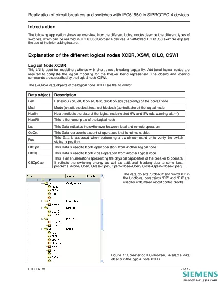
PTD EA 13 111 The following application shows an overview how the different logical nodes describe the different types of Beh Behaviour on off blocked test testblocked readonly of the logical n ID: 864174
Download Pdf The PPT/PDF document "Realization of circuit breakers and swit..." is the property of its rightful owner. Permission is granted to download and print the materials on this web site for personal, non-commercial use only, and to display it on your personal computer provided you do not modify the materials and that you retain all copyright notices contained in the materials. By downloading content from our website, you accept the terms of this agreement.


1 Realization of circuit breakers and swit
Realization of circuit breakers and switches with IEC61850 in SIPROTEC 4 devices PTD EA 13 -1/11- The following application shows an overview, how the different logical nodes describe the different types of Beh Behaviour (on, off, blocked, test, test-blocked) (read-only) of the logical node Health Health reflects the state of the logical node related HW and SW (ok, warning, alarm) NamPlt This is the name plate of the logical node Loc This Data indicates the switchover between local and remote operation OpCnt This Data represents a count of operations that is not reset able. Pos BlkOpn This Data is used to block 'open operation' from another logical node. BlkCls This Data is used to block 'close operation' from another logical node The data objects urcbA01and urcbB01 in Realization of circuit breakers and switches with IEC61850 in SIPROTEC 4 devices PTD EA 13 -2/11- Logical Node XSWI This LN is used for modeling switches without short circuit breaking capability, for example disconnectors, air break switches and ground switches. Additional logical nodes are req
2 uired to complete the logical modeling f
uired to complete the logical modeling for the switch being represented. The closing and opening commands are subscribed by the logical node CSWI. The available data objects of the logical node XSWI are the following: Data object Description Beh Behaviour (on, off, blocked, test, test-blocked) (read-only) of the logical node Mod Mode (on, off, blocked, test, test-blocked) (controllable) of the logical node Health Health reflects the state of the logical node related HW and SW (ok, warning, alarm) NamPlt This is the name plate of the logical node Loc This Data indicates the switchover between local and remote operation OpCnt This Data represents a count of operations that is not reset able. This Data is accessed when performing a switch command or to verify the switch status or position. BlkOpn This Data is used to block 'open operation' from another logical node. BlkCls This Data is used to block 'close operation' from another logical node SwTyp Switch type (Load Break, Disconnector, Earthing Switch, High Speed Earthing Switch) SwOpCap This is an enumeration representing the
3 physical capabilities of the switch to o
physical capabilities of the switch to operate. It includes additional blocking due to some local problems. (None, Open, Close, Open and Close) The data objects urcbA01and urcbB01 in the functional constraints DC and EX are used for unbuffered report control blocks. Figure 2: Screenshot IEC-Browser, available data objects in the logical node XSWI Realization of circuit breakers and switches with IEC61850 in SIPROTEC 4 devices PTD EA 13 -3/11- Logical Node CSWI This logical node is used to control circuit breakers and switches. The data object Posin the functional constraint CO will be changed by the Station Unit for operating the switch/circuit breaker. The operation is not possible if the interlocking conditions in the logical node CILO or the data objects Block Open and Block Close forbid to operate. The available data objects of the logical node CSWI are the following: Data object Description Beh Behaviour (on, off, blocked, test, test-blocked) (read-only) of the logical node Mod Mode (on, off, blocked, test, test-blocked) (controllable) of the logical node Hea
4 lth Health reflects the state of the log
lth Health reflects the state of the logical node related HW and SW (ok, warning, alarm) NamPlt This is the name plate of the logical node Loc This Data indicates the switchover between local and remote operation This Data is accessed when performing a switch command or to verify the switch status or position (for command you need FC Command, to show position you need FC Status). The data objects urcbA01and urcbB01 in the functional constraints RP and EX are used for unbuffered report control blocks. Figure 3: Screenshot IEC-Browser, available data objects in the logical node CSWI Realization of circuit breakers and switches with IEC61850 in SIPROTEC 4 devices PTD EA 13 -4/11- Logical Node CILO This logical node is used to enable a switching operation if the interlocking conditions are fulfilled. One instance per switching device is needed. At least all related switchgear positions have to be subscribed. The interlocking algorithm is a local issue and will be realized in the CFC logic of the SIPROTEC device. The available data objects of the logical node CSWI are th
5 e following: Data object Description Be
e following: Data object Description Beh Behaviour (on, off, blocked, test, test-blocked) (read-only) of the logical node Mod Mode (on, off, blocked, test, test-blocked) (controllable) of the logical node Health Health reflects the state of the logical node related HW and SW (ok, warning, alarm) NamPlt This is the name plate of the logical node The interlocking function itself determines the status of this data and thus permits the opening of the device when TRUE. The control service checks this value before he controls Open/Off a switch. EnaCls The interlocking function itself determines the status of this data and thus permits the closing of the device when TRUE. The control service checks this value before he controls Close/On a switch. The data objects urcbA01and urcbB01 in the functional constraints RP and EX are used for unbuffered report control blocks. Figure 4: Screenshot IEC-Browser, available data objects in the logical node CILO Realization in Siprotec devices: The mapping of the origin SIPROTEC parameter values to the IEC61850 data attributes is described in t
6 he PIXIT-file of the dedicated SIPROTEC
he PIXIT-file of the dedicated SIPROTEC relay (download of all PIXIT-files is possible at www.siprotec.com). The circuit breaker is often named Q0, the disconnector Q1 and the ground switch Q8 corresponding to German Standard DIN40719-2. Therefore these terms are used as the default prefixes for the logical nodes. Realization of circuit breakers and switches with IEC61850 in SIPROTEC 4 devices PTD EA 13 -5/11- With XCBR and XSWI it is possible to read the status of the switches, but no control. The control will be done with the logical node CSWI. The CSWI contains a data object called Pos. The values of the attributes of this object can be changed by a Station Unit with a command. If a switch object is created, there are always automatically three logical nodes created. The XCBR for a circuit breaker or XSWI for another kind of switch, the CSWI for controlling the circuit breaker or switch and the CILO to check the interlocking conditions. The LN CILO is not visible in the configuration matrix, but in the IEC 61850 station configurator or online via IEC-Browser. In the DIGSI
7 matrix normally there are predefined com
matrix normally there are predefined command lines with feedback for the different switches available. They are grouped in the matrix group Control Device. Use this way for a convenient and simple configuration, if applicable. The following example shows you the possibilities of the interlocking feature in SIPROTEC 4 devices: The circuit breaker (Q0) is only permitted to close, if the disconnector (Q1) is closed and the ground switch (Q8) is openedRefer to the input/output matrix. In the group control device the commands for the switching devices are indicated. Each command occupies two lines. Picture 5: The commands in the input/output matrix For example, the first line of the disconnector switch Disc. Swit. contains the command information which is routed to the output contacts. The second line is for the feedback Realization of circuit breakers and switches with IEC61850 in SIPROTEC 4 devices PTD EA 13 -6/11- signals which are derived via binary inputs. The command as a source for system interface to be operated by a station unit. The feedback as destination system interface
8 and CFC-logic for further processing.
and CFC-logic for further processing. Two binary inputs for feedback are required for double point indication i.e. if: - the switch device is opened=off (01) - the switch device is closed=on (10) - the switch device is in intermediate / not valid position (either 00 or 11). Controls without feedback can also be used; in this case interlocking will not be possible. For interlocking the feedback signals are the most important information. In this example, the interlocking must check the status of the disconnector (Q1) and the earth switch (Q8) before releasing a close command to the circuit breaker Q0. In picture 6 the CFC chart is shown. The status of the disconnector and earth switch is decoded with DI_TO_BOOL gates. Picture 6: application of interlocking in CFC The first DI_TO_BOOL gate decodes the closed position of the disconnector switch (Q1). The 2 DI_TO_BOOL gate decodes the open position of the ground switch (Q8). If both these conditions are valid, the AND gate will generate the signal for releasing the circuit breaker close command Brk Close. Realization of circuit breakers an
9 d switches with IEC61850 in SIPROTEC 4 d
d switches with IEC61850 in SIPROTEC 4 devices PTD EA 13 -7/11- The default settings already contain signals for interlocking (internal single point annunciations, see picture 5). For user defined signals these must first be created in the I/O matrix and routed to source CFC. Otherwise these will not be available for selection later. Ultimately the interlocking condition of the circuit breaker command must be allocated to the release signal derived with the logic in picture 6 ( see picture 7 ). In the input/output matrix you have to click with the right mouse button on the circuit breaker and choose the object propertiesThe release signal Control Device Brk Close is responsible for the switching ON the circuit breaker. Picture 7: Object properties of the circuit breaker For the control functions such as circuit breaker OFF or other devices the same procedure must be carried out with the relevant interlocking conditions. The default settings of SIPROTEC 4 devices always contain a CFC chart with standard interlocking functions. Realization of circuit breakers and switches with IEC61850
10 in SIPROTEC 4 devices PTD EA 13 -
in SIPROTEC 4 devices PTD EA 13 -8/11- Picture 8: Extended CFC chart for interlocking of several switching devices To create a logical node XCBR (if necessary) insert a control command in the matrix like in the figure below: Picture 9: Information catalog for different commands, indications Realization of circuit breakers and switches with IEC61850 in SIPROTEC 4 devices PTD EA 13 -9/11- Drag and drop the control command to the matrix. Two lines one for the command and the second one for the feedback appear automatically. Picture 10: object properties window of the created command for a circuit breaker Assign the information to the system interface, and then the object property window of this command appears automatically. Choose Circuit breaker as the switch type and give the logical node a prefix, e.g. Q0 and a suffix. As you can see this choice will automatically assign this control command to the logical nodes XCBR and CSWI (and CILO, but not listed here). In case of choosing another switch type, e.g. Disconnector the control command will automatically assigned to th
11 e logical nodes XSWI and CSWI (and CILO,
e logical nodes XSWI and CSWI (and CILO, but not listed here) as well: Realization of circuit breakers and switches with IEC61850 in SIPROTEC 4 devices PTD EA 13 -10/11- Picture 11: object properties window of the created command for a disconnector To send commands and receive feedback to/from the circuit breaker, configure both information to the assigned binary inputs and outputs: Picture 12: configuration of the source and destination of the circuit breaker Within the object properties window of the first command line you can select the signal used in the CFC to check the interlocking conditions. For Release for CLOSE and for TRIP you can choose one of the command lines out of the matrix. If no interlocking condition is used, the switching object can be operated directly. Realization of circuit breakers and switches with IEC61850 in SIPROTEC 4 devices PTD EA 13 -11/11- Picture 13: insert the interlocking conditions for the circuit breaker After updating the information to the IEC 61850 station configurator and updating the SIPROTEC device you can check the configurati