
TEEPC 25 May 2018 Electrolytic Capacitor Tests Summary Background work Motivation of the test Test objectives Test protocol Test Results Conclusions Capacitor banks for energy recovery Electrolytic Capacitors for Energy Storage Purposes ID: 1031561
Download Presentation The PPT/PDF document "Konstantinos Papastergiou" is the property of its rightful owner. Permission is granted to download and print the materials on this web site for personal, non-commercial use only, and to display it on your personal computer provided you do not modify the materials and that you retain all copyright notices contained in the materials. By downloading content from our website, you accept the terms of this agreement.


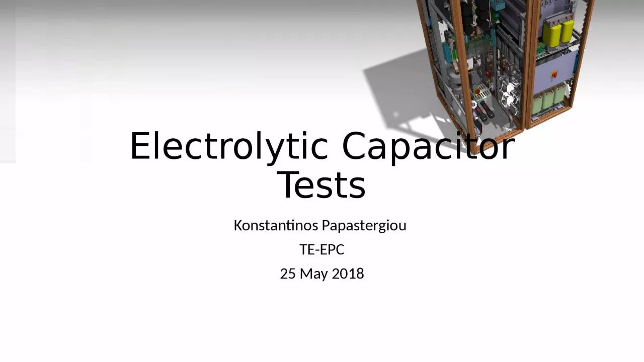
1. Konstantinos Papastergiou TE-EPC25 May 2018Electrolytic Capacitor Tests
2. SummaryBackground workMotivation of the testTest objectivesTest protocolTest ResultsConclusionsCapacitor banks for energy recovery
3. Electrolytic Capacitors for Energy Storage PurposesApplications: Energy recovery of power converters supplying magnets- SIRIUS power converter family (e.g. TT2 Consolidation Programme)- Future medium power converters with energy recovery capacitor banksBenefits:- Increased energy efficiency of power converters supplying magnets- Improved power quality from power networkSingle brick SIRIUS power converterMaster Thesis work by Luca Sburlino
4. Single Capacitor Ratings: Worst Case RequirementsCapacitor bankMin – max voltage600 V – 900 VCycle duration (freq.)1.2 s (0.833 Hz)Configuration3 series x 5 parallelSingle screw-terminal Al-ELCAP ratingsRMS voltage400 VRMS current11 APeak current50 AVoltage swing300 V – 206 VCapacitance≥ 29 mFAmbient temperature40 ºCMinimum Lifetime100’000 h operationWorst case cycle acting on single capacitorMaster Thesis work by Luca Sburlino
5. Construction TechnologyEnhanced heat dissipation by using:- Extended cathode (axial direction)- Corrugation (radial direction)- Thermal conductive glue (may clog safety vent)Screw-terminal aluminium electrolytic capacitor
6. Manufacturing ProcessIncrease capacitance density: Anode and cathode foils etching (1)surface increase of 60x for 400 V capacitorsObtain capacitor rated voltage: Anode foil forming (2)Vformation ≈ 540 V for 400 V capacitorsIncrease capacitor quality, reduce early failures: Ageing (7)Vr < Vageing < Vformation Manufacturing process
7. Lifetime Influences: Charge-Discharge ApplicationsTab-heating in charge-discharge applicationsCharge-discharge applications:Elevated heating on tabs.Consequences: Local electrolyte vaporisation and damage on tabs more likelyTransient Thermal, Electrical and Lifetime Analysis of Large-Can Al-ELCAPs,Cornell Dubilier – Sam G. Parler, Jr., P.E.
8. Lifetime Influences: Charge-Discharge ApplicationsAgeing and failure modes diagram
9. Motivation for the Tests by the manufacturerPrevious experience with capacitive energy storage shows the need to understand the failure mechanism of capacitors.To have enough input in order to decide compensatory safety measuresVisualisation of the cabinet (video) during the testVisualisation of the vapour release from the cabinet (video) during the testVisualisation of the test area (video), to assess the potential projection of debrisMeasurement of the voltage/current during the testMeasurement of the sound pressure at 1 m from the cabinetPhotos of the cabinet (exterior+interior) after the testDetailed photos of the capacitor bank after the testQualitative assesmnet of impact to the floor.
10. ObjectivesQualitative assessment of the impact of a capacitor failureVerify Sirius metallic enclosure withstand to a destructive failureQualitative assessment of the impact on surrounding equipmentFrom heat and fireFrom debris and flying partsFrom the electrolyte evaporation Identify the audible magnitude of a failure
11. Test ProtocolTest 1: Continuous rated peak voltage across a capacitorSingle point of failure will result in this conditionWithstand over long time to be determinedRepeat on three different samplesTest 2: Continuous over-voltage (x2) across a capacitorA double failure will result in this conditionWorst case if energy source not disconnectedRepeat on three different samplesTest 3: Reverse polarisationReverse polarisation of a capacitorMay occur as a result of manufacturing errorRepeat on three different samplesEDMS 1919992
12. Test setup descriptionTest 1 & 2Overvoltage on DUTWith and without external sourceTest 3Reverse polarisation of DUTGradual increment of source voltage
13. Test 1 Results: continuous peak voltageShot 1: 450V on DUT -> no failure during 1hShot 2: 550V on DUT -> instant destructive failureShot 3: gradual increase 450V to 520V on DUT:Failure at 520V after 1320sec
14. Test 2 Results: over-voltage (x2)Test 2Shot 1: 900V on DUT with external source -> failure after 73sShot 2: 900V on DUT, external source disconnected -> no failure, DUT operational after testShot 3: 900V on DUT, external source disconnected -> no failure, DUT operational after testShot 4: 900V on DUT with external source -> destructive failure
15. Test 3 Results: reverse polarisationShot 1: Reverse polarisation of DUT with external source -> failure, open vent
16. Summary of test resultsTest 1 & 2: single point of failureOver-voltage <37%** : No failure after 1 hour of exposureOver-voltage >37% with Sirius capacitor banks energy: Failure mode is uncertain Over-voltage >37% with Sirius capacitor bank energy and external energy source: Destructive failure mode after some time Test 3: polarity reversalFailure with open-vent after 900sec if source remains energised.** Over-voltage with respect to the application operating voltage
17. Sirius Capacitor Failure Tests - ConclusionsElectrolytic capacitors are prone to failure if exposed to over-voltage.There is no evidence that energy stored in a Sirius brick can cause by itself destructive failure or fire.A failure may become destructive in case an energy source remains energised after the event.Key findings:Destructive failure of capacitors (fumes, debris) is contained by the enclosure Destructive failure of capacitors has no structural impact on the Sirius metallic enclosureDestructive failure has limited impact on the equipment directly aboveThe peak observed sound level was 135.5db at 0.5 meter from the cabinet*Destructive is a failure that results on visible damage to the capacitor can or its surroundings*Reports and media in EDMS folder CERN-0000189820A report is circulated internally for approval and will be placed under CERN-0000189820