/
Report Documentation PageForm ApprovedOMB No. 0704-0188Public reportin Report Documentation PageForm ApprovedOMB No. 0704-0188Public reportin

Report Documentation PageForm ApprovedOMB No. 0704-0188Public reportin - PDF document

erica
erica . @erica
Follow
343 views
Uploaded On 2021-01-11

Report Documentation PageForm ApprovedOMB No. 0704-0188Public reportin - PPT Presentation

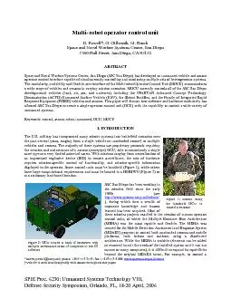
Standard Form 298 Rev 898 Prescribed by ANSI Std Z3918 different type of vehicle or monitor a different kind of sensor or to use a different map or video display the MRHA code itself has to be m ID: 829692

vehicle mocu vehicles control mocu vehicle control vehicles configuration display user interface modules figure information module core system protocol

Share:

Link:

Embed:

Download Presentation from below link

Download Pdf The PPT/PDF document "Report Documentation PageForm ApprovedOM..." is the property of its rightful owner. Permission is granted to download and print the materials on this web site for personal, non-commercial use only, and to display it on your personal computer provided you do not modify the materials and that you retain all copyright notices contained in the materials. By downloading content from our website, you accept the terms of this agreement.


Presentation Transcript

1 Report Documentation PageForm ApprovedOM
Report Documentation PageForm ApprovedOMB No. 0704-0188Public reporting burden for the collection of information is estimated to average 1 hour per response, including the time for reviewing instructions, searching existing data sources, gathering andmaintaining the data needed, and completing and reviewing the collection of information. Send comments regarding this burden estimate or any other aspect of this collection of information,including suggestions for reducing this burden, to Washington Headquarters Services, Directorate for Information Operations and Reports, 1215 Jefferson Davis Highway, Suite 1204, ArlingtonVA 22202-4302. Respondents should be aware that notwithstanding any other provision of law, no person shall be subject to a penalty for failing to comply with a collection of information if itdoes not display a currently valid OMB control number. 1. REPORT DATE 2006 2. REPORT TYPE N/A 3. DATES COVERED - 4. TITLE AND SUBTITLE Multi-Robot Operator Control Unit 5a. CONTRACT NUMBER 5b. GRANT NUMBER 5c. PROGRAM ELEMENT NUMBER 6. AUTHOR(S) 5d. PROJECT NUMBER 5e. TASK NUMBER 5f. WORK UNIT NUMBER 7. PERFORMING ORGANIZATION NAME(S) AND ADDRESS(ES) Space and Naval Warfare Systems Center, San Diego 5360 Hull Street 8. PERFORMING ORGANIZATIONREPORT NUMBER 9. SPONSORING/MONITORING AGENCY NAME(S) AND ADDRESS(ES) 10. SPONSOR/MONITOR’S ACRONYM(S) 11. SPONSOR/MONITOR’S REPORT 12. DISTRIBUTION/AVAILABILITY STATEMENT Approved for public release, distribution unlimited 13. SUPPLEMENTARY NOTES The original document contains color images. 14. ABSTRACT 15. SUBJECT TERMS 16. SECURITY CLASSIFICATION OF: 17. LIMITATION OF ABSTRACT SAR 18. NUMBEROF PAGES 8 19a. NAME OFRESPONSIBLE PERSON a. REPORT unclassified b. ABSTRACT unclassified c. THIS PAGE unclassified Standard Form 298 (Rev. 8-98) Prescribed by ANSI Std Z39-18 different type of vehicle or monitor a different kind of sensor or to use a different map or video display the MRHA code itself has to be modified. Two of the most valuable lessons SSC San Diego has learned are: (1) once you have an OCU that can control one type of unmanned system you will eventually need to modify it “just a little” to control another, and (2) each new vehicle will require extensive changes to the user interface, either due to an emergent customer requirement or the nature of the remote device. A new approach was needed to avoid time-consuming and expensive changes to a monolithic OCU to support new devices or technologies. MOCU has been designed to minimize these issues by using a more modular, scalable, and flexible architecture. Modularity allows for a breadth of functionality, such as communicating in unrelated protocols or displaying video with a proprietary video codec, and also makes third-party expansion of MOCU possible. Scalability enables MOCU to be installed on a wide range of hardware. MOCU also allows the user to define what information is displayed and determine what control is needed for each system.

2 The same core software is currently used
The same core software is currently used on a wide variety of projects, each utilizing these attributes in its own way. 2. ARCHITECTURE MOCU was created to provide the ability to simultaneously control and monitor multiple existing or newly developed heterogeneous unmanned systems. The term heterogeneous is used to describe vehicles which are dissimilar in both modality (land, air, sea, or undersea) and communications protocol. The goal is to not just minimally control, but to have full access to the vehicle/sensor and its various payloads. To achieve this goal, a modular, scalable approach was developed. The core (Figure 3c) acts as the glue to tie modules to other modules and to the user interface. Each (Figure 3a) represents a module which provides different functionality. Multiple modules of the same type can be utilized by the core. The interface (Figure 3b) between the module and the core is defined by the type of module. Each module of a certain type will conform to at least a subset of the interface definition for that type. The user interface, including display, joystick, and keyboard, is defined by a configuration file (Figure 3d). Multiple configuration files are loaded by the core but only one is used at a given time. Figure 3: The architecture of MOCU. 1 j 1 k I I Configuration file 2 Configuration file 1 Configuration file n User Interface Core b cd 2.1 Modular The main theme in the MOCU architecture is modularity. At the center is the core, which loads and manages modules (Figure 3). Modules contain specific functionality that modifies what MOCU can display and control (Figure 4). By achieving specific capabilities through associated modules, the core remains relatively constant. The core acts as the glue to tie information from the vehicles or sensors to the display. It manages information from the modules, such as waypoints, vehicle or sensor status, tracks, etc, and also handles the window framing in the user interface but does not draw to the internal windows directly (this is handled by the modules). The core manages each module according to its functionality. Each of the loaded modules has one or more predefined types (Table 1), depending on the functionality it performs, and must conform to at least a subset of the API for its predefined type(s). By standardizing the interface, multiple modules of the same type may be loaded, which allows MOCU to simultaneously control heterogeneous vehicles or display different types of maps. For instance, if MOCU loads both a JAUS protocol module and a STANAG 4586 protocol module, it would be able to simultaneously communicate with both JAUS-compliant and STANAG 4586-compliant vehicles. Type Description Currently Implemented C2 Link Communicate data and control to another command and control system Naval Undersea Warfare Center (NUWC) National Marine Electronics Association (NMEA) derivative, Composeable FORCEnet (CFn) Gauges Display data to the user in a graphical forma

3 t Microsoft’s Graphics Device Interface
t Microsoft’s Graphics Device Interface implementation GPS Import location of host for both differential correction and display on maps NUWC NMEA format, serial port using standard formats Elevation Imports elevation data for map data DTED Environment Retrieves information from the host computer, such as CPU usage and battery VIA chipset Map Display geo-referenced data to the user Aerial photo, DNC, S-57, C/JMTK, GeoTIFF, WVS Media Decode and display video and audio from a vehicle or sensor Indigo video bridge (6000 and 8000 series), MJPEG Planner Provides automated path planning from path database or circumnavigation Static from stored path database, dynamic path planner using DNC data Protocol Handle communication with vehicles or sensors JAUS (standard and SPARTAN), MRHA, iRobot TMR (PackBot and Gator), SMART Table 1: The types of modules supported by the core. To communicate with a vehicle or sensor, MOCU must load a protocol module, which then communicates with the vehicle and provides control when MOCU has requested it. MOCU supports a broad range of vehicle autonomy, from autonomous vehicles with obstacle avoidance to teleoperated vehicles to stationary sensors. As with all types of Video Ma Core Figure 4: In the modular MOCU architecture, multiple modules of each type may be loaded by the core. modules, the API between MOCU and protocol modules must define all of the functionality, but a specific module need only support the API functions that are required for a particular vehicle. For instance, the protocol module for the SPARTAN USV must handle waypoint navigation and radar controls; whereas, a stationary camera sensor might have a protocol module that only supports panning the camera. The creation of new modules is greatly simplified by the core handling the data management. For example, the map module type is vital for missions where geographic awareness is important. The core maintains the information on items on the maps and handles user input for actions such as panning or interfacing with a vehicle icon. There are many types of maps including both raster (Controlled Image Base (CIB), Compressed ARC Digitized Raster Graphic (CADRG), etc.) and vector (Digital Nautical Charts (DNC), World Vector Shoreline (WVS), etc.). The type of map(s) displayed within MOCU is chosen depending on the mission and modality of the vehicle (Figure 5). Some map packages display only one type of map, while others provide a very general capability but require extensive hardware to display the data at reasonable speeds. The interface to these map packages can be vastly different. With varying maps and requirements, the list of options for map modules is large. By handling the data management and user interface, each map module only needs to provide the map data and ability to draw lines and bitmaps in geographic coordinates. The modular architecture of MOCU allows for third party development, so that a module of any of the de

4 fined types can be created to completely
fined types can be created to completely alter the functionality of MOCU. For instance, a developer with a proprietary vehicle protocol may implement a protocol module using the defined interface and gain control of their vehicle in a fraction of the time it would take to write code for an entire OCU. No change is needed to the MOCU core when the standard interface is followed. 2.2 Scalable MOCU is inherently scalable due to its modular nature. As previously stated, most of the functionality within MOCU resides in its modules. Depending on the system requirements, the capabilities of MOCU are adjusted by adding or removing modules with no need to modify the core. The memory footprint and computational requirements are Figure 5: MOCU using both aerial photo and DNC maps to control and monitor land, sea, and air vehicles. Figure 7: Command and control station for FIRRE project. MOCU is part of the system to monitor and control multiple vehicles and stationary sensor suites. Figure 6: MOCU controlling two types of PackBots on a Panasonic CF-18 Toughbook. User input includes a determined by which modules are loaded. If the application requires a minimal installation, only the required modules to control or monitor a specific vehicle or sensor are installed on the target machine. For instance, the user may require small handheld hardware to control a teleoperated iRobot PackBot Scout (Figure 6). In this example, where only joysticks, video, and status are necessary, the OCU would consist of the MOCU core, PackBot protocol module, and PackBot media module. However, a larger control structure where multiple semi-autonomous vehicles communicating in different protocols and modalities may require more functionality, to include maps, vehicle status, planner and scheduler (Figure 7). MOCU can be reconfigured to run on a broad range of hardware, including small embedded processors, all using the same core and a specialized subset of available modules. 2.3 Flexible user interface The user interface, which includes the display and user input, is defined by XML configuration files (Figure 3). The display configuration specifies the location and types of maps, video, gauges, etc. The user input includes the mapping of the joystick, keyboard, and mouse to commands in MOCU. MOCU has two general modes of operation: monitor and . The user interface in both is defined by the configuration files discussed in section 2.4. One operator can use MOCU to monitor multiple vehicles and sensors, but at any given time, can only control one. Control of a particular vehicle is requested, and if granted by the vehicle, MOCU enters into control mode. In monitor mode, all the vehicles in communication with MOCU are shown geographically on all displayed maps (Figure 5). Vehicle status information is also presented for each vehicle along with the option to display video if the status gauge is available. No control is available to the vehicle or sensors while in monitor mode. A

5 t any point, the user can switch to cont
t any point, the user can switch to control mode by selecting a vehicle. While in control mode, MOCU has complete control of a vehicle or sensor and its payloads. More status information is available, and the vehicle or sensor can be controlled through teleoperation or by sending waypoints to the vehicle, depending on what the vehicle or sensor supports. MOCU uses configuration files to determine how the display is arranged and where user input is mapped. MOCU configures itself via the configuration files at runtime, so there is no need to recompile the core software to make changes or additions. For instance, changing the type of map displayed or adding a compass gauge to an existing display for a particular vehicle can be done by modifying an XML file with a standard text editor. Figure 8: (a) Example of a configuration for an unmanned sea vehicle. A DNC map and video are displayed along with various status in both graphical and textual form. (b) Example of a configuration for an unmanned ground vehicle. No map is displayed but video is prominent. A particular configuration file specifies the display layout in monitor mode. But in control mode, the current configuration is determined by the currently selected vehicle’s identity. MOCU attempts to find the configuration file that is most specific to that vehicle, starting with the vehicle name and progressing through model, class, manufacturer, protocol and finally, modality (UAV, USV, etc.). This allows one configuration to be used for all vehicles or a different user interface for each vehicle or the same interface for vehicles of the same modality, or any variation of these. For example, one configuration file can be used for all iRobot vehicles by specifying “iRobot” in a configuration file. Alternately, two separate configuration files can be created, one for the PackBot Scout and one for the Gator. MOCU will select the most specific configuration file for a particular vehicle. If one file is general (iRobot) and another is specific (iRobot Gator), MOCU will select the more specific configuration file over the more general file. The importance of having a flexible interface is derived from controlling and monitoring all types of vehicles and sensors. For sea vehicles, the operator will require digital nautical charts detailing features in the waterways (Figure 8a) whereas for ground vehicles, detailed terrain information is required. In some applications, map data is not needed and only video and status information are required (Figure 8b). In this instance, the display configuration would not include maps. The ability to easily modify the user interface is an important attribute of a truly common OCU. The layout of the display and mapping of the user input is generally customer specific. Each user has their own requirements as to which data is to be displayed and how it is arranged. By using runtime-loaded configuration files, each customer can see a different display but use the sa

6 me software. For example, some customers
me software. For example, some customers require the display be configurable by the user and have a Microsoft Windows application feel with docking, resizable windows. Others require the application run full screen, with no dynamic window configuration. Another example is the mapping of joystick buttons. Each vehicle typically provides different functionality, and the mapping of a joystick often reflects these special capabilities. With the configuration files, button 1 can be mapped to the “IR filter toggle” function for one vehicle and “laser pointer toggle” for another. Buttons in the display are accessed by the mouse or touch screen and are similarly configurable. Some vehicles provide more functionality than can be mapped using a feasible number of buttons (or axes on a joystick). Configuration modes assign a joystick to different functionalities (Figure 9). For instance, the vehicle may contain a camera with many features. If the user needs to control this functionality but only when the vehicle is stationary, the configuration file may describe two modes, one for teleoperation and another for control of the camera. The teleoperation mode might assign four buttons to drive the vehicle, while the camera mode might assign the same four buttons to “focus” and “zoom”. The configuration files specify how the information from the selected vehicle is presented on the display. Graphical gauges are used to give quick feedback, while textual gauges provide absolute values where appropriate. The style of a gauge, including dashboard, bar graph, textual or indicator, may be chosen to present the information in the format that is best suited to the nature of the data. 2.4 Interoperability The military is moving towards network-centric warfare where systems will be required to communicate with one another to share information. MOCU has the capability to communicate with existing command and control (C2) systems, and thus provide data from robotic assets to enrich the battle-space awareness. Communication with a C2 system may be unidirectional (in either direction) or bidirectional. The operator may receive a broader perspective with knowledge of surrounding systems, while systems up the chain benefit from information collected by the vehicles being monitored by MOCU. Figure 9: Two help images describing the same joystick in different configuration modes. In addition to monitoring the route that a particular vehicle is executing, the overarching C2 system can also send routes to the vehicle via MOCU. Depending on how MOCU is set up, these routes can either be immediately passed on unchanged, or they can be displayed to the MOCU operator as a C2-Link suggested route. In the latter case, the MOCU operator can accept the route as is, modify the route before sending it down to the vehicle, or reject the route outright. Whichever option the operator chooses, the action is reported to the C2 Link so that the higher level C2 system is aware of what the vehic

7 le is actually doing. Track data is one
le is actually doing. Track data is one of the most common types of information to be exchanged between a higher level C2 system and MOCU. For example, if a vehicle or sensor is tracking radar contacts, that information can be sent up to the C2 system to increase situational awareness for the area around each of the unmanned systems. Similarly, the C2 system can relay contact or track information down to MOCU. Since the devices that generate the contacts for a higher level C2 system are much more capable and accurate than those residing on typical unmanned vehicles this is a tremendous opportunity to increase the situational awareness of both the MOCU operator as well as any vehicles that are communicating with MOCU. This contact information can be used by the unmanned vehicle for path-planning and obstacle-avoidance purposes. MOCU was originally created in 2001 in response to a need for the Unmanned Ground Vehicle (UGVx) program for a small OCU capable of creating pixel-accurate routes for a small ground robot using aerial photography. This early version had a moving map that used aerial photos to display the location of the vehicle as well as allow the user to define routes. The status display was limited to textual output. In 2002, immediately after the conclusion of the UGVx program, SSC San Diego was contacted to create a similar OCU for the Night Vision and Electronic Sensors Directorate (NVESD) Remote Robotic Reconnaissance Vehicle (R3V) project under the Night Vision Cave and Urban Assault (NVCUA) ACTD. The requirements here were that the OCU had to run on an embedded processor with no moving parts (i.e., no hard disk), fit in a small backpack, and be able to simultaneously control an SSC San Diego URBOT and both an iRobot PackBot Scout and Explorer (Error! Reference source not found.). Graphical gauges were added to improve the user interface, and dependence on a mouse was removed to support increased mobility. The hardware joystick/button controllers could be swapped in or out so that the OCU hardware could be re-configured quickly to control vehicles with different capabilities (flippers, actuators, grippers, etc.). It was during this period that the first loadable modules were created: GaugesEnvironmentalSensors, and Protocols. The protocol modules were significant because although the URBOT uses the SMART protocol and the PackBots use a proprietary iRobot protocol, MOCU was able to control both of these vehicles simultaneously. In addition, the flexible user interface was created at this time because the PackBots and URBOT have significantly different capabilities. The SPARTAN ACTD work began toward the end of R3V in late 2003. The goal of the SPARTAN program is to field an Unmanned Surface Vehicle (USV). Rather than create another custom OCU, the SPARTAN team formed a working group to evaluate currently available OCUs and choose the one that best met their needs. After evaluating several different alternatives, the working group

8 decided MOCU was the most viable candida
decided MOCU was the most viable candidate. For the SPARTAN project, the primary user interface was through a Digital Nautical Chart (DNC), a product of the National Geospatial Intelligence Agency (NGA, formerly known as NIMA). SSC Charleston already had an existing DNC display application known as COGENT (COmmon GEospatial Navigation Toolkit) that could be integrated into MOCU and would become the first map module. An emerging robotics protocol standard known as JAUS (Joint Architecture for Unmanned Systems) was adopted and integrated into MOCU through the JAUS protocol module. The JAUS protocol was extended to handle messages required for controlling a USV. In addition, a radar interface was added that allowed MOCU to display radar contacts as well as overlay raw radar imagery directly on the chart. Later, a command and control module (C2 Link) was created that allowed MOCU to communicate with a higher level C2 program known as the Joint Unmanned Figure 10: Prototype of handheld OCU designed for NVESD. Systems Common Control (JUSC2), which provides status of unmanned systems to higher level C2 systems as well as allowing the higher level C2 system to give instructions to the unmanned vehicles. The Family of Integrated Rapid Response Equipment (FIRRE) program was the next to adopt MOCU in 2005. The purpose of the FIRRE program is to integrate UGVs, unattended ground sensors (UGSs) and ground surveillance radars (GSRs) into a system that provides force protection of high-value areas for forward-deployed forces. MOCU (known as Joint Battle Command and Control Station (JBC2S) under FIRRE) is being modified to monitor the status of ground sensors, monitor and control the GSRs and control the Tactical Amphibious Ground Support System (TAGS) vehicles. The JUSC2 and Navy’s Littoral Combat Ship (LCS) programs will be using MOCU to control USVs. The LCS program is using MOCU for both the Mine Warfare (MIW) mission as well as the Antisubmarine Warfare (ASW) mission. MOCU is also being used to support a number of Joint Robotics Program (JRP) projects at SSC San Diego. These include controlling UGVs, a USV, a UAV and a UUV as well as a weapon system. In December 2005, SSC San Diego demonstrated some of MOCU’s capabilities to representatives from government and industry by showing simultaneous control of robots operating on land, sea and air. All of these assets were controlled from a single computer, running a single instance of MOCU, by a single operator. 4. FUTURE OF MOCU MOCU has continued to be adopted by ever more unmanned systems programs, which will inevitably lead to continued innovation and additional functionality. There are plans to interface to additional UAVs and to add features to enhance the control and mission planning for UAVs, such as route verification using DTED and other terrain databases, as well as a STANAG 4586 protocol module. There will certainly be additional types of modules developed and additional variants of the existing

9 types, possibly including new types of m
types, possibly including new types of map modules with 3D display capabilities, automatic mission planning modulespath planning modules, generic payload modulesC2Link modules will also be extended to interface with additional command and control architectures and will include the integration of more service-oriented-architecture (SOA) approaches such as XML, DDS and JMS. Two of these efforts are underway now. One is to interface MOCU to the SSC San Diego CFn which is an instantiation of the Navy’s future FORCEnet Services Infrastructure (FSI). The other is LCS in which MOCU will interface to the Integrated System Services (ISS), a data and services distribution system. SSC San Diego is also planning on developing a distributed control architecture, where multiple MOCUs communicating through a common network would have the ability to pass vehicle, sensor and database information between them as well as control of individual vehicles. There is a growing objective within the unmanned system community for a common OCU that will control many if not all of the vehicles in a particular mission. MOCU is currently capable of controlling multiple vehicles, but there is a definite limit on the number of systems one operator can control or even supervise. This limit is primarily based on the level of autonomy of the vehicles and the payloads and the mission complexity. In a situation where there are more vehicles in operation than one operator can control, it would be useful to start up a second identical MOCU, have it download all of the vehicle and mission data, and then have that additional operator take control of some of the assets. 5. CONCLUSION Even as unmanned systems gain continuing acceptance on the battlefield, most require a stovepipe OCU to control them. MOCU provides the capability to control and monitor multiple heterogeneous systems while remaining flexible to handle different missions. MOCU was created to be modular and scalable to prevent it from becoming a large software program that requires an inordinate amount of effort to make a relatively small change. As technology advances, MOCU will be able to advance by adding or replacing functionality. The incorporation of new functionality need not be limited to SSC San Diego, but can be added seamlessly through third-party development. *darren.powell@navy.mil; phone: 1 619 553 2553; fax: 1 619 553 6188; www.spawar.navy.mil/robots †Vehicle is used interchangeably with sensor throughout this paper. stems Technology VIII, Defense Security Symposium, Space and Naval Warfare Systems Center, San Diego ), during which time a wealth of corporate knowledge and lessons learned has been acquired. Most of these robotics projects resulted in the creation of custom operator control units, of which the Multiple Resource Host Architecture Figure 1: Marine using the handheld OCU to control a PackBot Figure 2: OCU located in back of HMMWV with multiple screens and racks of computers to run C2 software