
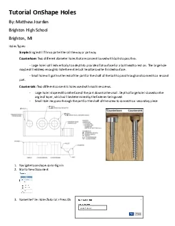
HolesBy Matthew JourdenBrighton High SchoolBrighton MIHolesTypes SimpleSingle drill Thru a part either all the way or part wayCounterboreTwo different diameter holes that are concentric used with bolt ID: 880422
Download Pdf The PPT/PDF document "Tutorial OnShape" is the property of its rightful owner. Permission is granted to download and print the materials on this web site for personal, non-commercial use only, and to display it on your personal computer provided you do not modify the materials and that you retain all copyright notices contained in the materials. By downloading content from our website, you accept the terms of this agreement.


1 Tutorial OnShape Holes By: Matthew Jo
Tutorial OnShape Holes By: Matthew Jourden Brighton High School Brighton, MI Holes Types: Simple: Single drill Thru a part either all the way or part way Counterbore: Two different diameter holes that are concentric used with bolts to pass thru. - Large hole is drilled vertically to a depth to provide a flat surface for a bolt head to rest on. The large hole maybe drilled deep enough to hide the entire bolt head below the finished surface. - Small hole will go thru the rest of the part for the shaft of the bolt to pass through and connect to a second part. Countersink: Two different concentric holes used with machine screws. - Large hole is tapered from the face of the part down to the small. Depth of large hole is based on the angle of taper, w hich will be determined by the fastener being used. - Small Hole
2 may pass through the part for the shaft
may pass through the part for the shaft of the screw to connect to a secondary piece 1. Navigate to ons hape .com � Sign in 2. Start a New Document 3. Name the File: Holes Tutorial � Press Ok Holes Tutorial 4. Design the following block 5. Counterb ore Hole Two ways to create Counterbore holes . Create Both Holes on the part Option 1: Extrude Two Extrusion will be created. In the real world the large hole would have to be cut first so that surface will be left to find the center point of the small point to make the two holes concentric. On CAD software it does not matter which is cut first. Large Hole a. Select Sketch � Select the Top Surface � Press n Key to rotate view � Rena me Sketch: Large Hole � Select Circle � Draw the Circle and sho
3 wn � Place Dimensions � Mo
wn � Place Dimensions � Modify Values � Green Check to Accept b. Select Sketch Large Hole from Model Tree � Select Extrude Icon � Rename Extrude: Large Hole � Select Remove Tab � Set Depth to .5 � Green Check to accept Extrude Height = 1 Small Hole a. Select Sketch � Select the Top Surface or the bottom of the Large Hole does not matter � Press n Key to rotate view � Rename Sketch: Small Hole � Select Circle � Draw the Circle and shown � Place the cursor at the center of the Large Hole (This will make the holes concentric so if the counterbore hole needs to move then the user will just need to change the dimensions on Large Hole and the Small Hole will follow) � Wait until center point appears � Lef t Click &#x
4 0000; Draw Circle � Set Diameter
0000; Draw Circle � Set Diameter .500 � Green Check to Accept b. Select Small Hole from Model Tree � Select Extrude Icon � Rename Extrude to Small Hole � Cut Through All � Green Check to Accept Extrude Option 2: Hole Tool a. Rotate to the top View (Select Top from the navigator or Shift + 5) � Select Hole Tool � Change the Name: CBORE � Change Hole T ype to C ounter bore � Set the Hole Dimensions as shown � Select Mate Connector � Select the Bottom Left corner of the part Wait for Center Point to Appear before drawing the circle for the small hole Set Diameter to .5 Concentric Circles 4. Select Bottom Left Corner 3. Select Mate Connector 1. Hole Type Counterbore 2. Set Sizes b.
5 S elect Mate Connector from the Sketch
S elect Mate Connector from the Sketch Points to place Holes � Change X and Y Coordinate to what is shown c. Green Check to Accept the Hole 6. Countersink Hole Technically there is two ways to make a countersink hole. Using the Hole Tool and Revolve Tool. The hole tool is the typical way to create this type of hole. Using the revolve tools is much more difficult and will take up more time than it i s worth. a. Select Hole Tool � Select Top Surface � Press n Key to rotate part � Change Name of Hole to Csink � Change Hole Type to Counter Sink � Change the Values as shown � Select the Mate Connector � Select the Bottom Left Corner of the Part Select Mate Connector 4. Select Bottom Left Corner 4. Select Mate Connector 2. Hole Type Counte
6 rbo re 2. Set Sizes b. Select Mat
rbo re 2. Set Sizes b. Select Mate Connector from the Sketch Points to place Holes � Change X and Y Coordinate to what is shown 7. Layout a. Select + Sign at the bottom Left Corner of screen � Select Create Drawing � Show OnShape drawings Template � A - Size Title Block Landscape BHS b. Place Top View i. Scale 3:4 c. Place Center Points for the 3 Holes d. Front View Full Section: Select the Section Tool � Select Horizontal Tab from the Section View Properties � Select one of the center points of the three holes � Drag Cursor down to place the front view Select Mate Connector Select New � Create Drawing Select Horizo ntal Select Center Point of 1 of the 3 holes Section Tool e. Place Centerlines using Edge to Edge Centerline Tool NOT
7 E: Be sure to elongate the centerline to
E: Be sure to elongate the centerline to traverse the entire hole Drawing Should Look as Follows 8. Dimensions Holes need 3 Dimensions i. Leader Line: Diameter of Hole and Depth (if hole does not go thru all) ii. Two Locators: Measuring to the center of hole b. Dimension Counterbore : Add the Dimension Shown. Notice the leader line arrow is pointing at the l arger hole. This is important for clarity. The dimension should read Drag Cursor down to create the Front View Centerline Tool c. Dimension the middle Counterbore hole d. Dimension Countersink: Dimension is similar to Counterbore in terms of the order of info e. Place the Locator Dimensions Completed Drawing NOTE: Middle Hole Dimension Missing � Student should place Submission Share Document to jourdem@brightonk12.c