
Rob Williamson Supervisors Chris Warsop ISIS Ivan Konoplev JAI Contents Introduction ISIS Synchrotron Loss Mechanisms at ISIS Headtail RampD Damping Systems Summary and Plans Introduction ID: 778989
Download The PPT/PDF document "Beam Instabilities at the ISIS Neutron &..." is the property of its rightful owner. Permission is granted to download and print the materials on this web site for personal, non-commercial use only, and to display it on your personal computer provided you do not modify the materials and that you retain all copyright notices contained in the materials. By downloading content from our website, you accept the terms of this agreement.


Slide1
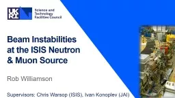
Beam Instabilities at the ISIS Neutron & Muon Source
Rob Williamson
Supervisors: Chris Warsop (ISIS), Ivan
Konoplev
(JAI)
Slide2Contents
Introduction
ISIS Synchrotron
Loss Mechanisms at ISIS
Head-tail R&D
Damping Systems
Summary and Plans
Slide3Introduction
800 MeV
Synchrotron (50 Hz)
H
-
ion source, 35
keV
H
-
RFQ,
665
keV
H
-
Linac, 70 MeV
Target Station 1 (40 pps)
Target Station 2 (10 pps)
Slide4Circumference: 163 mEnergy:
70–800 MeVRepetition Rate: 50 HzIntensity:
~3x10¹³ pppPower: ~190 kWInjection: 220 µs, 130
turn, charge exchangeExtraction: single turn, verticalBetatron Tunes:
(
Q
x
,
Q
y
) = (4.31
, 3.83
), programmableBeam Losses: Injection: 2%, Trapping: <3%,
Acceleration/Extraction: <0.5%RF system: h=2, 1.3-3.1 MHz, 160 kV/turn h=4, 2.6-6.2 MHz, 80 KV/turn
ISIS Synchrotron
Extraction
Injection
Time (
ms)
Slide5Tune shift ≥0.5 over 0 - 0.5 msHalf integer limitWhat is the mechanism for beam loss?
Non-linear driving termsMeasurements show non-linear resonance linesConformal vacuum vessel, however beam envelope varies with tuneNon-negligible image termsNon-linear magnet fields
Loss Mechanisms at ISIS - Transverse Space Charge
BG Pine
CM Warsop
Slide6Current intensity limitDual harmonic operationSymmetric bunches unstableNo longer able to cure with tune ramp
Driven by impedancesResistive wallNarrowband cavity structuresLoss Mechanisms at ISIS
- Head-tail Instability
Normal beam +
Θ
shift
Large loss!
Normal beam
Low loss
ISIS Beam Bunches at ~ 2
ms
Sum signal
Difference signal
Beam Loss vs Time 0-5
ms
Loss!
Measurements with V Kornilov (GSI)
Slide7Transverse instability Wakefield excited by head of bunch interacts with particles in the same bunch
Head-Tail Instability
Position monitor signal
I(t)*y(t)
I(t)
Time
Time
Characterised by mode structure in position monitor difference signal
Variation with
chromaticity
Tune varies with energy offset
Phase shift between head and tail
Increasing Chromaticity
Slide8ExperimentsSimplify to single harmonic RF operationLow intensity => ignore space chargeTheory and simulations with resistive wall predict
mode number m=2 (two nodes)Observations show m=1 (one node)What is the driving impedance?
Head-Tail R&D* Modified CERN code
Measurement Vs HEADTAIL* Simulation
:
Difference Signal
Slide9Beam based impedance measurementsCoasting beam at injection energyGrowth rate from BPM difference signalVary tune to scan frequencyGrowth rate proportional to impedance
ObservationsResistive wallLow frequency narrowband impedance
Head-Tail R&D
Effective Impedance Vs Frequency
BPM Difference Signal, FFT & Sideband
Slide10Use existing components: BPM, ferrite loaded kickerLLRF electronics for processing signalsFPGA for ADC/DAC, digital filter, delays and gainDynamically updated 3-tap FIR filter allows for correct phase for kick through acceleration
Head-Tail Damping System
Vertical pickup
(R4VM1)
Vertical
Q-kicker
Phase Advance Correction
Programmable
Fine
D
elay
Power
Amplifier
G
ain
Slide11Vertical head-tail motion 1 - 2.5 ms through acceleration cycleSuppressed byRamping vertical tune
Asymmetric longitudinal distributionControl of longitudinal and vertical paintingHead-tail effectively damped and beam losses reducedFurther commissioning required
Experimental Results
Slide12Improve simulation model & compare with experimentImprove machine model to aid in impedance diagnosis and damping operationAutomatic tune measurement
Summary
High intensity R&D is an important subject of study for ISIS and future high intensity proton machines
Half integer studies
Image effects
Non-linear magnet
terms
Plans
Head-Tail Studies
Experiments
Measurements of the instability at ISIS
Impedance measurements
Simulations
Development/implementation of in-house code
Impedance modelling
Damping System
Slide13