
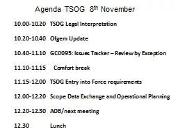
Prepared by DrYMohamed Shuaib Associate Professor amp HEADEEE BSA CRESCENT IS ampT VandalurChennai 48 Department of EEEBSA CRESCENT ISamp T ID: 1000305
Download Presentation The PPT/PDF document "REACTIVE POWER c ompensation in power sy..." is the property of its rightful owner. Permission is granted to download and print the materials on this web site for personal, non-commercial use only, and to display it on your personal computer provided you do not modify the materials and that you retain all copyright notices contained in the materials. By downloading content from our website, you accept the terms of this agreement.


1. REACTIVE POWERcompensation in power systemPrepared by:Dr.Y.Mohamed ShuaibAssociate Professor & HEAD/EEEBSA CRESCENT IS &T, Vandalur,Chennai - 48 Department of EEE/BSA CRESCENT IS& T 1
2. Compensation in power systemThe maintenance of constant frequency requires an exact balance between the overall power supplied by generators and the overall power absorbed by the load irrespective of voltage.Voltage level are very sensitive to the flow of reactive power, therefore the control of reactive power is important. This is the stage of reactive compensation.When there is a focus in compensation of individual loads, then it is known as Load compensation.Department of EEE/BSA CRESCENT IS& T 2
3. LOAD COMPENSATIONLoad compensation is used to improve the quality of the supply at a particular load or group of load.Compensating equipment such as power factor correction equipment is usually installed near to the consumer premises.In load compensation the main objectives are,Power factor correction Improvement of voltage regulationLoad balancing Department of EEE/BSA CRESCENT IS& T 3
4. POWER FACTOR CORRECTIONPower factor correction and load balancing are desirable even when the supply voltage is stiff.Ideally ,the reactive power requirement of a load should be provided locally rather than drawing reactive component of current from a remote power station.Most industrial loads have lagging power factor i.e. they absorb reactive power. Hence the load current increases i.e. tend to be larger than is required to supply the real power alone.Department of EEE/BSA CRESCENT IS& T 4
5. Only the real power is ultimately useful in energy conservation and excess load current.When load power factors are low , generators and distribution network current cannot be used at full efficiency.So the control of voltage becomes difficult throughout the network.Supply tariffs to the industrial towers usually prefer low power factor loads , encouraging the use of power factor correction equipment.Department of EEE/BSA CRESCENT IS& T 5
6. VOLTAGE REGULATIONIn this the supply utilities are usually bound by statute to maintain the voltage within the obtained limits (at the rate of +5% or -5%).Rapidly varying loads could cause voltage dips hazardous to the operation of protective equipment .The most obvious way to improve voltage regulation would be the “strengthen”, the power system by increasing the size and no. of generating units.This approach is costly .According to the maximum demand for the real power and to manage the reactive power by the means of “compensators”.Department of EEE/BSA CRESCENT IS& T 6
7. LOAD BALANCINGMost AC power systems are three phase and are designed for balanced operation.Unbalanced operation gives rise to components of current in wrong phase sequence (negative and zero phase sequence).Harmonics problems often arise together with the compensation problem and some types of compensators even generate harmonics which must be suppressed internally and filtered.Department of EEE/BSA CRESCENT IS& T 7
8. IDEAL COMPENSATORSIdeal compensators would ,Supply the exact reactive power requirement of the load Present a constant voltage characteristics at its terminalBe capable of operating independently in three phases.Department of EEE/BSA CRESCENT IS& T 8
9. FAULT LEVELFault level (or) short circuit level is a term used to describe the “strength” of the power supply.it has the ability to provide both current and voltage.It is defined as : Fault level = O.C.voltage × short circuit current (v/ph) .The fault level result is used t select the size of the circuit breaker in the power system.Circuit breaker must interrupt the fault current.When the contact of the circuit breaker are separating there is an arc which must be extinguished , i.e. it depends on both current and voltage.The rating of a circuit breaker should always exceed the fault level at the point where the circuit breaker is connected, otherwise it may not be capable of interrupting the fault current. This would be dangerous. Short circuit level, S=E*E/XS.Department of EEE/BSA CRESCENT IS& T 9
10. The load can be measured by its current I, but in power systems it is the reactive volt amperes of the load that is held chiefly responsible for the voltage drop.∆V=E-V=ZsI where I is the load current. I=P-jQ/V; V=V+j0 ∆V=(Rs+jXs)(P-jQ/V) =(Rsp+XsQ/V)+j (XsP-RsQ/V) =∆Vr+ ∆Vx.∆V depends on both real and reactive power.By adding a component in parallel in the load it is possible to maintain | V |= |E |.Department of EEE/BSA CRESCENT IS& T 10
11. |E|²=[V+RsP+XsQs\V] ²+ [XsP-RsQs/V] ²The value for Qr require to achieve this constant voltage condition is found by solving the above equation.Qs with V= |E|; then Qr=Qs-Q.Purely reactive compensator can eliminate voltage cause by changes in both real and reactive power of the load, [P=EsEr/Xs *sin δ] Qr=[Er* Es cos δ-Er/Xs]Department of EEE/BSA CRESCENT IS& T 11
12. COMPENSATING VOLTAGE CONTROLDepartment of EEE/BSA CRESCENT IS& T 12
13. when the load draws current from the supply , the terminal voltage v falls below the open circuit value E. The relationship between V and the load current I is called system load line.Department of EEE/BSA CRESCENT IS& T 13
14. PHASOR DIAGRAM (uncompensated) Department of EEE/BSA CRESCENT IS& T 14
15. REFERENCES:E.Acha,V.G.Agelidis,O.Anaya Lava, “ Power Eletronic Control in Electronical systems “, T.J.E.Miller, Elsevier Newnes Power Engineering SeriesDepartment of EEE/BSA CRESCENT IS& T 15
16. Department of EEE/BSA CRESCENT IS& T 16THANK YOU