

Many of the terms used in these slides can be found in the CT Terminology Lexicon httpwwwaapmorgpubsCTProtocolsdocumentsCTTerminologyLexiconpdf Last updated 18 November 2013 Disclaimer ID: 532054
Download Presentation The PPT/PDF document "AAPM Computed Tomography Radiation Dose ..." is the property of its rightful owner. Permission is granted to download and print the materials on this web site for personal, non-commercial use only, and to display it on your personal computer provided you do not modify the materials and that you retain all copyright notices contained in the materials. By downloading content from our website, you accept the terms of this agreement.


Slide1
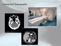
AAPM Computed Tomography Radiation Dose Education Slides
Many of the terms used in these slides can be found in the CT Terminology Lexiconhttp://www.aapm.org/pubs/CTProtocols/documents/CTTerminologyLexicon.pdf
Last updated: 18 November 2013Slide2
Disclaimer
The information contained herein is current as of the date shown on the title slideThe master version of these slides is located at:http://www.aapm.org/pubs/CTProtocols/documents/EducationSlides.pptx
Modification of the content of these slides
is allowed
.
The modified content, including indirect or unintentional changes in the accuracy or meaning of related content, becomes the sole responsibility of the person/organization creating and/or using the edited version.
Neither the AAPM nor the manufacturers participating in creating this slide set assume any responsibility for edited versions of these slides, or for content of oral presentations associated with the original or edited slides.Slide3
Motivation
These slides are provided to aid in understanding the factors that affect radiation dose in CT studiesImage patients wisely and
gently
A CT study should use as little radiation as possible,
while still meeting the image quality needs of the exam
A CT study that is non-diagnostic because the radiation dose is too low may require rescanning the patient – increasing the total patient dose
imagegently.org
imagewisely.orgSlide4
Outline
What is Dose?Acquisition Parameter SettingsDose Modulation and ReductionDose DisplaySlide5
What Is Dose?
Volume Computed Tomography Dose Index (CTDIvol) is a standardized parameter to measure S
canner
R
adiation
O
utputCTDI
vol is NOT patient doseCTDIvol is reported in units of mGy for either a 16-cm
(for head exams) or 32-cm (for body exams) diameter acrylic phantomFor the same technique settings, the CTDIvol
reported for the 16-cm phantom is about twice that of the 32-cm phantom
The reported CTDI
vol
is based on measurements made by the manufacturer in a factory setting
In these slides, the term "patient dose" is used to describe the absorbed dose to a patient, while the generic term "dose" refers to CTDI
volSlide6
How is CTDIvol related to patient dose?
CTDIvol is not patient doseThe relationship between the two depends on many factors, including patient size and composition
AAPM Report 204
introduces a parameter known as the Size Specific Dose Estimate (SSDE) to allow estimation of patient dose based on
CTDI
vol
and patient sizeFor the same
CTDIvol, a smaller patient will tend to have a higher patient dose than a larger patient
What is Dose?Slide7
How is CTDIvol related to patient dose?
Both patients scanned with the same
CTDI
vol
Patient dose will be higher for the smaller patient
CTDI
vol
= 20 mGy
CTDI
vol
= 20 mGy
120 kVp at 200 mAs
120 kVp at 200 mAs
32 cm Phantom
32 cm Phantom
What is Dose?Slide8
How is CTDIvol related to patient dose?
Smaller patient scanned with a lower
CTDI
vol
Patient doses will be approximately equal
What is Dose?
CTDI
vol
=
10
mGy
CTDI
vol
= 20 mGy
120 kVp at
100
mAs
120 kVp at 200 mAs
32 cm Phantom
32 cm PhantomSlide9
Size Specific Dose Estimate (SSDE)
AAPM report 204 describes a method to calculate SSDE using CTDIvol Conversion factors based on patient size (e.g., AP or lateral width, effective diameter) are provided to
estimate
patient dose for a patient of that size
However, SSDE is still not the exact patient dose, as factors such as scan length and patient composition may differ from the assumptions used to calculate SSDE
SSDE is not dose to any specific organ, but rather the mean dose in the center of the scanned volume
What is Dose?Slide10
32 cm Phantom
32 cm Phantom
How is CTDI
vol
related to patient dose?
Patients have equivalent SSDE
CTDI
vol
=
10
mGy
SSDE = 13.2 mGy
CTDI
vol
= 20 mGy
SSDE = 13.2 mGy
120 kVp at
100
mAs
27 cm
9 cm
What is Dose?
120 kVp at 200 mAsSlide11
Why Use CTDIvol?
CTDIvol provides information about the amount of radiation used to perform the studyCTDI
vol
is a useful index to track across patients and protocols for quality assurance purposes
CTDI
vol
can be used as a metric to compare protocols across different practices and scanners when related variables, such as resultant image quality, are also taken in account The ACR Dose Index Registry (DIR) allows comparison across institutions of
CTDIvol for similar exam types (e.g., routine head exam)
What is Dose?Slide12
Dose Length Product
The Dose Length Product (DLP) is also calculated by the scanner DLP is the product of the length of the irradiated scan volume and the average CTDIvol over that distance
DLP has units of mGy*cm
What is Dose?Slide13
Useful Concepts/Terms
The relationships between acquisition parameters and CTDIvol described in the following slides assume all other parameters are held constant
The relationship between a parameter and CTDI
vol
is often described as
proportional
in some wayThe symbol
µ is used to indicate “
proportional to”Directly proportional means that a change in the parameter results in the same change in CTDIvol
Example: Doubling the rotation time from 0.5 to 1.0 seconds will double the CTDI
vol
Inversely proportional means that a change in a parameter has the opposite effect on CTDI
vol
Example: Doubling the pitch from 1 to 2 will reduce the CTDI
vol
by halfSlide14
Acquisition Parameter Settings
Acquisition Parameters define the technique that will be used and how the scan will proceedAcquisition Parameters are set in the user interface where scans are prescribedChanging a single Acquisition Parameter while holding everything else constant will typically affect the CTDI
vol
for that scan
The following slides describe what that affect is for each parameterSlide15
Scan Mode
CT Scanners offer a variety of Scan Modes which describe how the table moves during an exam Scan Modes include
Axial
Helical or Spiral
Dynamic
The Acquisition Parameters that affect CTDIvol may change amongst different
Scan Modes
Acquisition Parameter SettingsSlide16
Dynamic Scan Mode Notes
In the Dynamic Scan Mode multiple acquisitions covering the same body region are acquired. Examples of these study types include:Perfusion StudiesBolus Tracking StudiesTest Bolus StudiesDynamic Scans often have large CTDI
vol
values because the scanner reports the sum of the CTDI
vol
values from each rotation
The reported CTDIvol is NOT skin dose or organ dose
Acquisition Parameter SettingsSlide17
Table Feed/Increment
Is the movement of the table through the bore of the scanner over a full 360 degree rotationUnits: millimeters/rotation or millimeters/secondThe parameter is known both as Table Feed (helical/spiral acquisition) &
Table Increment
(axial acquisition)
Table Feed affects CTDI
vol
through its inclusion in Pitch (discussed later)
Acquisition Parameter SettingsSlide18
Detector Configuration
Is the combination of the number of data channels and the width of the detector associated with each data channel The Detector Configuration determines the Beam Width or Beam Collimation (
nT
), which is the number of channels (n) times the detector width associated with each data channel (T)
For a selected detector width per data channel, a smaller total Beam Collimation usually has a higher CTDI
vol
than a larger Beam Collimation
Example: On a 16 slice scanner with a detector width per channel of 1.25 mm, a collimation of 4x1.25mm is generally less dose efficient than a collimation of 16x1.25mm
Users should monitor CTDIvol
values when changing detector configuration
Acquisition Parameter SettingsSlide19
Acquisition Parameter Settings
Detector ConfigurationSlide20
Pitch
Is the Table Feed per gantry rotation divided by the beam width/collimationPitch is the ratio of two distances and therefore has no units
Users should monitor other parameters when changing
Pitch.
T
he scanner may or may not automatically compensate for changes in
Pitch
(for example, by changing the tube current) to maintain the planned CTDIvol.
CTDI
vol
µ
1
/Pitch:
Hitachi, Toshiba (no AEC)
CTDI
vol
independent of Pitch:
GE, Siemens, Philips,
Neusoft
, Toshiba (AEC)
Acquisition Parameter SettingsSlide21
Pitch
CTDIvol may not change in the expected manner if the scanner automatically adjust other parameters when the pitch is changedThe relationships between CTDIvol and pitch for the different vendors are described below CTDIvol
inversely proportional to change in pitch:
Hitachi,
NeuroLogica
CTDI
vol constant when pitch is changed due to changes to other parameters: GE,
Neusoft, Philips and SiemensThe relationship between CTDI
vol and pitch depends on scan mode or Software version: ToshibaSlide22
Pitch <
1
Beam Width has some overlap at each view angle from rotation to rotation
Pitch =
1
No overlap of Beam Width at each view angle and no view angles not covered at certain table positions
Pitch >
1
Some view
a
ngles are not covered by the beam width at certain table positions
Acquisition Parameter Settings
PitchSlide23
Exposure Time per Rotation
Is the length of time, in seconds, that the X-ray beam is “on” during a gantry rotation It takes into account the gantry rotation time and angular acquisition rangeUnits: seconds
Users should monitor other parameters when changing
Exposure Time per Rotation.
The scanner may or may not automatically compensate for changes in
Exposure Time per Rotation
(for example, by changing the tube current)
CTDI
vol µ Exposure Time per Rotation
Hitachi,
NeuroLogica
, Toshiba (no AEC)
CTDI
vol
independent of Exposure Time per Rotation:
GE,
Siemens, Philips,
Neusoft
, Toshiba (AEC)
Acquisition Parameter SettingsSlide24
Exposure Time per Rotation
CTDIvol may not change in the expected manner if the scanner automatically adjust other parameters when the exposure time per rotation is changedThe relationships between CTDIvol and exposure time per rotation for the different vendors are described below
CTDI
vol
proportional to change in parameter:
Hitachi and
NeuroLogica
CTDIvol constant when the parameter is changed due to changes to other parameters: GE, Neusoft
, Philips and SiemensThe relationship between CTDIvol and the parameter depends on scan mode or Software version:
ToshibaSlide25
Tube Current
Determines the number of electrons accelerated across the x-ray tube per unit timeUnits: milliAmperes (mA)CTDIvol is directly proportional to
Tube Current
CTDI
vol
µ
Tube Current
Acquisition Parameter SettingsSlide26
Tube Potential
Is the electrical potential applied across the x-ray tube to accelerate electrons toward the target materialUnits: kiloVolts (kV or kVp)CTDIvol
is
approximately
proportional to the square of the percentage change in
Tube Potential
Acquisition Parameter Settings
n ≈ 2 to 3Slide27
Tube Current Time Product
Is the product of Tube Current and the Exposure Time per RotationUnits: milliAmpere-seconds (mAs)CTDIvol is directly proportional to
Tube Current Time Product
CTDI
vol
µ
Tube Current Time Product
Acquisition Parameter SettingsSlide28
Effective Tube Current Time Product
Is the product of the Tube Current and the Exposure Time per Rotation divided by the PitchUnits: milliAmpere-Seconds (mAs)CTDIvol is directly proportional to
Effective Tube Current Time Product
CTDI
vol
µ
Effective Tube Current Time Product
Acquisition Parameter SettingsSlide29
Field Of Measurement
Is the diameter of the primary beam in the axial plane at the gantry iso-centerUnits: millimeters (mm)CTDIvol
may decrease with a decrease in the
Field of Measurement
The relationship is vendor specific
Users should monitor the CTDI
vol
values when changing the Field of Measurement
Acquisition Parameter SettingsSlide30
Beam Shaping Filter
Is the scanner component that modifies the energy spectrum and spatial distribution of the primary beamBeam Shaping may include a bow tie filter and/or flat filtersCTDI
vol
is affected by a change in
Beam Shaping Filters
The relationship is vendor and filter specific
Users should monitor CTDI
vol values when changing the Beam Shaping Filter
Acquisition Parameter SettingsSlide31
Acquisition Parameter Settings Summary
Parameter
Relationship
to CTDI
vol
Scan Mode
Changes in the Scan Mode may affect CTDI
vol
Table Feed/Increment
Table Feed affects CTDI
vol
through its inclusion in Pitch
Detector Configuration
Decreasing
the Beam Collimation typically, but not always, increases the
CTDI
vol
Pitch
CTDI
vol
relationship to pitch
is vendor dependent
Exposure Time Per Rotation
CTDI
vol
relationship to exposure time per rotation is vendor dependent
Tube Current
CTDI
vol
µ
Tube Current
Tube
Potential
CTDI
vol
µ
(kVp
1
/kVp
2
)
n
n ~ 2 to 3
Tube Current Time Product
CTDI
vol
µ
Tube Current Time Product
Effective Tube Current Time Product
CTDI
vol
µ
Effective Tube Current Time Product
Field of Measurement
Changes in the Field of Measurement may affect CTDI
vol
Beam Shaping Filter
Changes in the Beam
Shaping Filter may
affect CTDI
volSlide32
Dose Modulation and Reduction
Many CT scanners automatically adjust the technique parameters (and as a result the CTDIvol) to achieve a desired level of image quality and/or to reduce doseDose Modulation and Reduction techniques vary by scanner manufacturer, model and software version Slide33
Automatic Exposure Control (AEC)
Automatically adapts the Tube Current or Tube Potential according to patient attenuation to achieve a specified image qualityAutomatic adjustment of Tube Current may not occur when Tube Potential is changed
Centering the patient in the gantry is VITAL for most AEC systems
AEC aims to deliver a specified image quality across a range of patient sizes. It tends to increase CTDI
vol
for large patients and decrease it for small patients relative to a reference patient size
The use of Automatic Exposure Control may decrease or increase
CTDI
vol depending on the patient size and body area imaged and image quality requested
Dose Modulation and ReductionSlide34
Image Quality Reference Parameter
Is the AEC parameter that is set by the user to define the desired level of image quality Changing the Image Quality Reference Parameter will affect the CTDIvol
The effect on
CTDI
vol
when changing the Image Quality Reference Parameter is vendor dependent
Dose Modulation and ReductionSlide35
Image Quality Reference Parameter
A change in the Image Quality Reference Parameter will affect the CTDIvolSetting the parameter for “increased” image quality (e.g., lower noise) will result in more doseSetting the parameter for “decreased” image quality (e.g., more noise) will result in less dose
Dose Modulation and ReductionSlide36
Angular Tube Current Modulation
Is an AEC feature that adjusts the Tube Current as the x-ray tube rotates around the patient to compensate for attenuation changes with view angleAngular Tube Current Modulation is used to adjust the Tube Current to attempt to deliver similar dose to the detector at all view angles
The use of Angular Tube Current Modulation may decrease or increase CTDI
vol
depending on the
patient
size and body area imaged
and
image quality requested
Dose Modulation and ReductionSlide37
Angular Tube Current Modulation
Angular Tube Current Modulation uses information from one or two view localizers
Dose Modulation and ReductionSlide38
Longitudinal Tube Current Modulation
Is an AEC feature that adjusts the Tube Current as patient attenuation changes in the longitudinal direction The CT Localizer Radiograph is used to estimate patient attenuation
The use of Longitudinal Tube Current Modulation may decrease or increase
CTDI
vol
depending on the patient size and body area imaged and image quality requested
Dose Modulation and ReductionSlide39
Longitudinal Tube Current Modulation
Longitudinal Tube Current Modulation uses information from
one or two view localizers
Dose Modulation and ReductionSlide40
Angular and Longitudinal Tube Current Modulation
Is an AEC feature that incorporates the properties of both Angular and Longitudinal Tube Current Modulation toAdjust the Tube Current based on the patient’s overall attenuation
Modulate the Tube Current in the angular (X-Y) and longitudinal (Z) dimensions to adapt to the patient’s shape
The use of Angular and Longitudinal Tube Current Modulation may decrease or increase CTDI
vol
depending on the patient size and body area imaged and image quality requested
Dose Modulation and ReductionSlide41
Angular and Longitudinal Tube Current Modulation
Dose Modulation and ReductionSlide42
ECG-Based Tube Current Modulation
Is an AEC feature used with prospectively gated cardiac imaging that adjusts the Tube Current based on the phase within the cardiac cycleThere are important heart rate considerations to take into account when using prospective gating
The use of ECG-Based
Tube Current
Modulation with prospective gating will decrease
CTDI
vol
compared to
retrospective gating
Dose Modulation and ReductionSlide43
ECG-Based Tube Current Modulation
Dose Modulation and Reduction
Radiation On
Multiple heart beats and table positions may be required to collect all of the data required to reconstruct the FOV including the heartSlide44
Organ-Based Tube Current Modulation
Is an AEC feature that allows for the tube current to be decreased or turned off over radiosensitive organs on the patient periphery, such as the breasts or eye lensesTo maintain image quality, tube current may need to be increased at other view angles
The use of Organ-Based Tube Current Modulation may reduce the absorbed dose to organs at the surface of the body but may increase the absorbed dose to other organs
Dose Modulation and ReductionSlide45
Gantry
Gantry
Conventional
Organ-Based Modulation
Dose Modulation and Reduction
Organ-Based Tube Current ModulationSlide46
Automatic Tube Potential Selection
Is an AEC feature that selects the tube potential according to the diagnostic task and patient size in order to achieve the desired image quality at a lower CTDIvol
The use of Automatic Tube Potential Selection is intended to decrease CTDI
vol
while achieving the image quality required for a specific diagnostic task and patient attenuation
Dose Modulation and ReductionSlide47
Automatic Tube Potential Selection
Tube Potential is not modulated in the same fashion as Tube CurrentIt does not change with different tube positions (view angles) around the patientThe Tube Potential for a specific patient, anatomic region and diagnostic tasks is selected and held constant for that acquisition, though it may be changed to a different tube potential for a different diagnostic task
Dose Modulation and ReductionSlide48
Iterative Reconstruction
Is a feature that uses the information acquired during the scan and repeated reconstruction steps to produce an image with less “noise” or better image quality (e.g., higher spatial resolution or decreased artifacts) than is achievable using standard reconstruction techniques
The use of Iterative Reconstruction by itself may not decrease CTDI
vol
; with use of Iterative Reconstruction, image quality will change
and this may allow a reduction in the CTDI
vol
by adjusting the acquisition parameters used for the exam
Dose Modulation and ReductionSlide49
Iterative Reconstruction
Iterative Reconstruction may be completed using data in Image Space, Sinogram Space or a Model Based ApproachChanging/Turning On the %/Level of the iterative reconstruction used may or may not affect the CTDIvol
of the scan and will affect the image quality of the final set of images
In consultation, the Radiologists and Medical Physicists at an institution may adjust the acquisition parameters for studies reconstructed using iterative reconstruction
based on the imaging task, the patient population, the desired image quality, dose concerns and the needs of the interpreting Radiologist
Dose Modulation and ReductionSlide50
Noise Reduction Using Other Post Processing Software
Other commercially available products can be used to reduce image noise in already reconstructed imagesIn consultation, the radiologists and medical physicists may adjust the acquisition parameters to reduce the CTDI
vol
used for
studies
that will be processed using these products, taking into consideration the imaging task and patient population, dose concerns,
and the needs of the interpreting radiologist(s)
Dose Modulation and ReductionSlide51
Dose Display
Information about the CTDIvol planned for each scan is typically displayed before the exam on the user consoleInformation about the CTDI
vol
delivered
by each scan
is typically
reported in a data page or DICOM structured dose reportDose information provided after the exam typically also includes the DLP and the CTDI phantom size. These may also be included in information displayed before the scan.Slide52
Display of Planned CTDIvol
CTDIvol is displayed before a study is performed based on the selected technique parameters
It is important to check
CTDI
vol
before a study is performed to ensure that the output of the scanner is appropriate for the specific patient and diagnostic task
CTDI
vol is displayed for each planned acquisition
Dose DisplaySlide53
Post Study Data Page
Following the completion of a study, a Post Study Data Page is created that includes information on the delivered CTDIvol and DLP and the phantom size used to calculate these values
Information is displayed for each series
Dose DisplaySlide54
Post Study Data Page - CTDIvol
CTDIvol is displayed
for each series after a study is performed and is calculated based on the technique factors used to acquire the data
It is useful to check
CTDI
vol
after a study is performed to ensure that the output of the scanner was as expected
CTDIvol
is displayed for each completed acquisition
Dose DisplaySlide55
Post Study Data Page - DLP
DLP is displayed for each series after a study is performed and is calculated based on the technique factors and scan length used
DLP is displayed for each completed acquisition and is typically summed for all of the acquisitions
Dose DisplaySlide56
Post Study Data Page – CTDI Phantom
The CTDI Phantom used for each acquisition in the study is typically displayedDifferent phantoms may be used to calculate the CTDIvol
for different acquisitions in the same study (and may vary by vendor)
Head and C-Spine Example
Body Phantom used to report CTDI
vol
for C-Spine portion of examHead Phantom used to report CTDIvol
for Head portion of exam
Dose DisplaySlide57
Summing Dose Report Values
CTDIvol values for separate series are NOT to be summed to give a “total” CTDIvol for a studyThis is especially true if the series cover different anatomic regions
DLP is typically summed over all series in the Post Study Data Page to provide an estimate of the total patient exposure
Extreme care should be taken when considering summed DLPs because different phantoms may have been used to calculate the CTDI
vol
values used to determine DLP
A medical physicist should be contacted if patient specific dose estimates are required
Dose DisplaySlide58
Dose Notification Levels
Notification Levels may be set on a CT scanner for each series within an exam protocolIf the planned CTDIvol is above the
Notification Level
and triggers the notification, the user has the opportunity to edit or confirm the technique settings
Notification Levels
may be exceeded when appropriate for a specific patient or diagnostic task (e.g., in very large patients or contrast bolus monitoring scans)
Dose DisplaySlide59
Dose Alert Levels
Dose Alert Levels require specific action by the operator to continue scanningDose Alert Levels are typically much higher than Notification Levels and take into account all series within the exam
Triggering a
Dose Alert
requires that the operator confirm the protocol and settings are correct by entering in his or her name. Optionally, sites may require that the operator provide a brief explanation in the provided field
Dose DisplaySlide60
Radiation Dose Structured Reports
Radiation Dose Structured Reports (RDSRs) are provided in newer software versions in a defined DICOM formatThey provide the most complete set of information regarding the irradiating events
The reports are very detailed and require an RDSR viewer for easy visualization of relevant information
Dose DisplaySlide61
Questions
Please contact the medical physicist providing support for your CT practice, your lead technologist, supervising radiologist or manufacturer’s application specialist with questions regarding these important topics and concepts.Slide62
Acknowledgements
AAPMDianna Cody, Dustin Gress, Michael Heard, Jim Kofler, Cynthia McCollough, Mike
McNitt
-Gray, Bob
Pizzutiello
, Mark
SupanichACRMark Armstrong, Penny Butler, Dina HernandezASRT
Virginia LesterDICOMDavid Clunie, Kevin O’Donnell
FDAThalia MillsSlide63
Acknowledgements
GEJohn JaeckleHitachiMark SilvermanPhilips
Amar Dhanantwari
Neusoft
Keith Mildenberger
Neurologica
Donald Fickett
SiemensChristianne
LiedeckerToshibaKristen Boedecker
MITA
Brian Abraham