
g ADD eax5 Add 5 to contents of accumulator No memory reference to fetch data Fast Can have limited range in machines with fixed length instructions Immediate Addressing and Small Operands A great many immediate mode instructions use small operands 8 ID: 33447
Download Pdf The PPT/PDF document "Chapter Instruction Sets Addressing Mod..." is the property of its rightful owner. Permission is granted to download and print the materials on this web site for personal, non-commercial use only, and to display it on your personal computer provided you do not modify the materials and that you retain all copyright notices contained in the materials. By downloading content from our website, you accept the terms of this agreement.

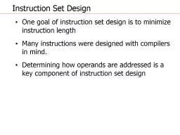


1 Chapter 11 Instruction Sets: Addressing Modes and Formats Computer Organization and Architecture Instruction Set Design One goal of instruction set design is to minimize instruction length Another goal (in CISC design) is to maximize flexibility Many instructions were designed with compilers in mind Determining how operands are addressed modes is a key component of instruction set design Addressing Modes Different types of addresses involve tradeoffs between instruction length, addressing flexibility and complexity of address calculation Common Addressing Modes Immediate Direct Indirect Register Register Indirect Displacement (Indexed) Implied (Stack, and a few others) Immediate Addressing Operand value is part of instruction Operand is one address field e.g. ADD eax,5 Add 5 to contents of accumulator No memory reference to fetch data Fast Can have limited range in machines with fixed length instructions Immediate Addressing and Small Operands A great many immediate mode instructions use small operands (8 bits) In 32 or 64 bit machines with variable length instructions space is wasted if immediate operands are required to be the same as the register size Some instruction formats include a bit that allows small operands to be used in immediate instructions ALU will zero - extend or sign - extend the operand to the register size Direct Addressing Address field contains address of operand Effective address (EA) = address field (A) e.g. add ax, count or add ax,[10FC] Look in memory at address for operand Single memory reference to access data No additional calculations to work out effective address 2 Direct Addressing in x86 architecture Intel x86 is a segmented architecture, so a segment register is involved in EA computation even if using the flat memory model Example Intel direct address instructions mov [0344], bx ; ds:[bx ] add [00C018A0], edx ; note add to mem pushd [09820014] ; note mem to mem inc byte ptr [45AA] ; compute in mem cmp es:[0342], 1 ; segment override Memory - Indirect Addressing Memory cell pointed to by address field contains the address of (pointer to) the operand EA = (A) Look in A, find address (A) and look there for operand X86 Memory Indirect Addressing Memory indirect addressing is very restricted in x86 architecture Transfer of control instructions only: CALL and JMP Examples: func1 dw ? func2 dw ? CALL [func1] Or JMP [func2] Cascaded Indirect Addressing Rarely used e.g. EA = (((A))) Implemented by using one bit of full - word address as an indirect flag Allows unlimited depth of indirection Requires multiple memory accesses to find operand; hence slower than any other type of addressing Register Addressing (1) Operand(s) is(are) registers EA = R Register R is EA (not contents of R) There are a limited number of registers Therefore a very small address field is needed Shorter instructions Faster instruction fetch X86: 3 bits used to specify one of 8 registers Register Addressing (2) No memory access needed to fetch EA Very fast execution Very limited address space Multiple registers can help performance Requires good assembly programming or compiler writing Note: in C you can specify register variables register int a; This is only advisory to the compiler No guarantees 3 Register Indirect Addressing Similar to memory - indirect addressing; much more common EA = (R) Operand is in memory cell pointed to by contents of register R Large address space (2 n ) One fewer memory access than indirect addressing Register Indirect Addressing Displacement Addressing EA = A + (R) Combines register indirect addressing with direct addressing Address field hold two values A = base value R = register that holds displacement or vice versa Types of Displacement Addressing Relative Addressing Base - register addressing Indexing Relative Addressing Sometimes called PC - relative addressing EA = A + (PC) Address field A treated as 2 s complement integer to allow backward references Fetch operand from PC+A Can be very efficient because of locality of reference & cache usage But in large programs code and data may be widely separated in memory Base - Register Addressing A holds displacement R holds pointer to base address R may be explicit or implicit e.g. segment registers in 80x86 are base registers and are involved in all EA computations x86 processors have a wide variety of base addressing formats mov eax,[edi + 4 * ecx ] sub [bx+si - 12],2 4 Indexed Addressing A = base R = displacement EA = A + R Good for accessing arrays EA = A + R R++ Iterative access to sequential memory locations is very common Some architectures provide auto - increment or auto - decrement Preindex EA = A + (R++) Postindex EA = A + (++R) X86 Indexed Addressing Autoincrement only with string instructions: Example : rep movsd Semantics es:[edi ] - ds:[esi ] esi - esi +/ - 4 ;DF determines + or - edi - edi +/ - 4 ecx - ecx - 1 Combine register pairs with optional displacement mov eax,[edi + 4 * ecx ] sub [bx+si - 12],2 Stack Addressing Operand is (implicitly) on top of stack e.g. PUSH POP X87 is a stack machine so it has instructions such as FADDP ; st(1) - st(1) + st(0); pop stack ; result left in st(0) FIMUL qword ptr [ bx ] ; st(0) - st(0) * 64 integer pointed to ; by bx Pentium Addressing Modes Virtual or effective address is offset into segment Starting address plus offset gives linear address This goes through page translation if paging enabled 12 addressing modes available Immediate Register operand Displacement Base Base with displacement Scaled index with displacement Base with index and displacement Base scaled index with displacement Relative Pentium EA Calculation ARM Addressing Modes A typical RISC characteristic is a small and simple set of addressing modes ARM departs somewhat from this convention with a relatively rich set of addressing modes But Load and Store are the only instructions that can reference memory Always indirect through a base register plus offset Three alternatives Offset Preindex Postindex 5 Offset Addressing Offset added or subtracted from value in base register Example: store byte, base register is R1 and displacement is decimal 12. This is the address where the byte from r0 is stored Preindex Addressing Memory address formed same way as offset addressing, but the memory address is written back to the base register after adding or subtracting the displacement With preindexing the writeback occurs before the store to memory Postindex Addressing Like preindex addressing but the writeback of the effective address occurs after the store Indexed Addressing Operands Previous examples had immediate values but the offset or displacement can also be in another register If a register is used then addresses can be scaled The value in the offset register is scaled by one of the shift operators Logical Shift Left / Right Arithmetic Shift Right Rotate Right Rotate Right Extended Amount of shift is an immediate operand in the instruction Arithmetic and Logical Instructions Use register and immediate operands only For register addressing one of the register operands can be scaled by one of the five shift operations mentioned previously Branch Instructions Only form of addressing is immediate Branch instruction contains a 24 - bit immediate value For address calculation this value is shifted left by 2 bits so the address is on a word boundary This provides a range of 26 bits so we have backwards or forwards branches of 32MB (2 25 ) 6 Load/Store Multiple Load/Store multiple loads or stores a subset of general purpose registers (possibly all) from/to memory List of registers is specified in a 16 - bit field in the instruction (one bit/register) Memory addresses are sequential; low address has lowest numbered register Found addressing modes: Increment/decrement before/after Base reg specifies a main memory address Inc/Dec starts before/after the first memory access Useful for block loads/stores; stack operations and procedure or function entry and exit sequences Instruction Formats Defines the layout of bits in an instruction Includes opcode and includes implicit or explicit operand(s) Usually there are several instruction formats in an instruction set Huge variety of instruction formats have been designed; they vary widely from processor to processor Instruction Length The most basic issue Affected by and affects: Memory size Memory organization Bus structure CPU complexity CPU speed Trade off between a powerful instruction repertoire and saving space with shorter instructions Instruction format trade - offs Large instruction set =� small programs Small instruction set =� large programs Large memory =� longer instructions Fixed length instructions same size or multiple of bus width =� fast fetch Variable length instructions may need extra bus cycles Processor may execute faster than fetch Use cache memory or use shorter instructions Note complex relationship between word size, character size, instruction size and bus transfer width In almost all modern computers these are all multiples of 8 and related to each other by powers of 2 Allocation of Bits Determines several important factors Number of addressing modes Implicit operands don t need bits X86 uses 2 - bit mode field to specify interpretation of 3 - bit operand fields Number of operands 3 operand formats are rare For two operand instructions we can use one or two operand mode mode indicators X86 uses only one 2 - bit indicator Register versus memory Tradeoff between # of registers and program size Studies suggest optimal number of between 8 and 32 Most newer architectures have 32 or more X86 architecture allows some computation in memory Allocation of bits Number of register sets RISC architectures tend to have larger sets of uniform registers Small register sets require fewer opcode bits Specialized register sets can reduce opcode bits further by implicit reference (address vs. data registers) Address range Large address space requires large instructions for direct addressing Many architectures have some restricted or short forms of displacement addressing Ex: x86 short jumps and loops, PowerPC 16 - bit displacement addressing Address granularity Size of object addressed. Typically 8,16, 32 and 64 instruction variants 7 PDP - 8 Very simple machine and instruction set Has one register (the Accumulator) 12 - bit instructions operate on 12 - bit words Very efficient implementation 35 operations along with indirect addressing, displacement addressing and indexing in 12 bits The lack of registers is handled by using part of the first physical page of memory as a register file PDP - 8 Memory References Main memory consisted of 4096 words divided into 32 128 - word pages Instructions with a memory reference had a 7 - bit address plus two modifier bits (leaving 3 bits for opcode !) Z/C bit Page 0 or current page (with this instruction) D/I bit Direct or Indirect addressing In addition the first 8 words of page 0 are treated as autoindex registers Note that memory - indirect addressing was used because processor had no index registers Instruction Formats A 3 - bit opcode and three types of instructions For opcodes 0 5 (6 basic instructions) we have single address mem ref with Z/C I/D bits Opcode 6 is I/O with 6 device - select bits and 3 operation bits Opcode 7 defines a register reference or microinstruction Three groups, where bits are used to specify operation (e.g., clear accumulator) Forerunner of modern microprogramming PDP - 8 Instruction Format PDP - 10 Designed to be a large scale time - sharing machine Emphasis on ease of programming even at the expense of additional hardware Design considerations 1. Orthogonality between opcodes and EA computations (EA computed in the same way regardless of opcode ) 2. Completeness: each data type ( int , fixed point, real) has a complete and identical set of operations 3. Direct Addressing in place of base + displacement addressing PDP - 10 Instruction Format 36 bit word and instruction length Single fixed instruction format 9 - bit opcode allows 512 operations; 365 were used 2 address instructions - one operand is GP register (16 regs = 4 bits) 2 nd operand 18 - bit address field Indirection available for mem sizes � 2^18 Provides indexing for iterative processing 18 bit address field makes immediate addressing attractive 8 Fixed and Variable Length Instructions Fixed length instructions can provide compactness and efficiency at the cost of flexibility (PDP - 8) or can utilize space inefficiently (PDP - 10) Variable length instructions can provide variety and flexibility in a compact format Cost occurs in processor complexity Trend until RISC was for variable length instructions; performance factors have reversed the trend Note that instruction length should be a multiple of word length; if you fetch max length you might get multiple instructions Intel x86 architecture does not follow this principle PDP 11 Variable length instruction format 8 16 - bit GP regs (one is SP, one is PC) 13 instruction formats Opcodes are 4 - 16 bits; 0,1,2 addresses Register references are 6 bits: 3 for reg , 3 for addressing mode Rich set of addressing modes Instructions are 16, 32 or 48 bits long PDP - 11 Instruction Format VAX Design Philosophy Most architectures provide a fairly small number of fixed instruction formats Addressing mode and opcode are not orthogonal Instructions typically limited to reg/mem , reg/reg etc Only 2 or 3 operands max can be accommodated; some instructions inherently require more (ex: integer division with 2 inputs and 2 outputs) VAX design principles were: 1. All instructions should have the natural number of operands 2. All operands should have the same generality in specification VAX Instructions Highly variable instruction format Opcode is one or two bytes long First by FF or FD indicates two byte opcode Followed by 0 to 6 operand specifiers Minimum instruction length is one byte Maximum is 37 bytes! Operand Specifiers At a minimum, 1 byte in which leftmost 4 bits are the address mode specifier except literal mode (00 followed by 6 literal bits) 4 bits specify one of 16 registers Operand specifier can be extended by immediate or displacement 8 32 bits Indexed addressing mode 0010 + 4 bit index reg id, followed by base address 8 - 32 bits 9 Example 6 operand instruction ADDP6 OP1, OP2, OP3, OP4, OP5, OP6 Adds two packed decimal strings Op1 and op1 are length and start addr of one string; op3 and 4 are second string Result is stored in length/location op5, op6 VAX Instruction Examples Pentium Instruction Format ARM Instruction Formats All instructions are 32 bits long and follow a regular format First four bits are condition codes Next three specify general type of instruction For most instructions other than branches next five bits are an opcode and/or modifier bits Remaining 20 bits are for operand addressing The very regular structure simplifies the design of instruction decode units ARM Instruction Formats S = For data processing instructions, signifies that the instruc tion updates condition codes S = For load/store multiple, signifies whether execution is rest ricted to supervisor mode P, U, W = bits that distinguish between different types of addre ssing_mode B = Distinguishes between an unsigned byte (B==1) and a word (B= =0) access L = For load/store instructions, distinguishes between a Load (L ==1) and a Store (L==0) L = For branch instructions, determines whether a return address is stored in the link register Data Processing Immediate The data processing immediate format provides a great range of values by specifying both an immediate value and a rotate value The 8 bit immediate value is expanded to 32 bits and then rotated by twice the 4 - bit rotate value 10 Thumb Instruction Set A re - encoded subset of the ARM instruction set Designed to increase performance of ARM implementations that use a 16 - bit or narrower memory data bus and provide better code density 32 - bit instructions are re - encoded into 16 - bit instructions Thumb Instruction Set Differences All instructions are unconditional (so cc field is unused saving 4 bits) All arithmetic and logical instructions update the condition flags saving 1 bit Thumb has a subset of operations with a 2 - bit opcode plus 3 - bit type field saving 2 bits Remaining 9 - bits come from reductions in operand specifiers . Ex: Can reference only r0 - r7; using only 3 bits for register references Immediate values do not include a 4 bit rotate field Thumb Instructions The ARM processor can execute a mixture of ARM and Thumb instructions A bit in the Processor Control Register specifies instruction type