
Energy Calibration Workshop EPOL group K Oide CERNKEK S Aumon P Janot D El Kechen T Lafevre A Milanese T Tydecks J Wenninger F Zimmermann CERN ID: 778742
Download The PPT/PDF document "FCC- ee beam polarization and" is the property of its rightful owner. Permission is granted to download and print the materials on this web site for personal, non-commercial use only, and to display it on your personal computer provided you do not modify the materials and that you retain all copyright notices contained in the materials. By downloading content from our website, you accept the terms of this agreement.


Slide1
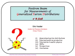
FCC-ee beam polarization and Energy CalibrationWorkshop
EPOL group: K Oide CERN/KEK, S. Aumon, P. Janot , D. El Kechen, T. Lafevre, A. Milanese, T. Tydecks, J. Wenninger, F. Zimmermann, CERN W. Hillert, D Barber DESY, D. Sagan, CornellG. Wilkinson, OxfordE Gianfelice-Wendt, FERMILABA Blondel , M Koratzinos, GENEVAP. Azzurri (Pisa)M Hildreth, Notre-Dame USAI Koop , N Muchnoi, A Bogomyagkov, S. Nikitin, D. Shatilov BINP; NOVOSIBIRSK
https://indico.cern.ch/event/669194/
see
my
other
slides and the workshop site for
summary
and
complete
info
Slide211/17/2017Alain Blondel Physics at the FCCs
2ConclusionsWe had a very sucessful workshop and unveiled and number of aspects of the question of energy calibration that are of great interest. Several good news -- running scenario, pilot bunches Touschek limited to ~few 1010 e+- /bunch -- wigglers (8 3-pole-units per beam) -- polarimeter/spectrometer set-up (new) -- polarization levels at Z and W -- direct measurements of energy spread and energy asymmetries -- smallness of
effect of beamstrahlung and RF -- etc. etc.
--
started
writing
the CDR! 25 pages and
typing!some difficulties-- opposite sign vertical dispersion-- possible difficulty with depolarizer.
THANK YOU!
see
all the slides for more information!
Slide311/17/2017Alain Blondel Physics at the FCCs
3There is a concern that low Qs value will make Qs resonances so close that (de)polarization disappears. Eliana and Ivan independently checked the possible effect.
The Qs
issue
at the W
with
Qs
= 0.08
W,
Qs
= 0.024
Eliana
, at the Z
Qs
=0.025
Ivan K, at 61GeV
Qs
=0.02
Similar
polarization
level
,
smoother
curves
.
Slide4FCC-ee at 45.6 GeV, Qs=.025, w=1·10-4, d
ν=0.5·10-82/ε’=0.46
Scan time:
T
= 260.8 s
With nominal
Qs=.
025
at Z. And with strong depolarizer
w=1·10
-4
.
My simple fit gives the resonance frequency with an error
Δν
= -
0.00011
.
But, in fact, the transition zone here is very narrow and is centered to the right spin tune value very well.
Slide5FCC-ee at 80.41 GeV, Qs=.05, w=1.41·10-4, d
ν=0.5·10-82/ε’=0!
Scan time:
T
= 260.8 s
Try to increase the depolarizer strength up to
w=1.41·10
-4
.
But not clear, trustable picture we see. Simple fit gives the resonance frequency with an error
Δν
= -
0.0004
.
I think, the last two plots show that the synchrotron tune at W should be made much higher. Its minimal acceptable value is
Qs=.075
, or even higher!
Slide611/17/2017Alain Blondel Physics at the FCCs
6Hardware requirements: wigglers Polarization wigglers 8 units per beam, as specified by Eliana Gianfelice B+=0.7 T L+ = 43cm L-/L+ = B+/B- = 6 at Eb= 45.6 GeV and B+= 0.67 T => P=10% in 1.8H Eb = 60 MeV Ecrit=902 keV
placed e.g. in dispersion-free straight section H and/or F
Given
the long
polarization
time at Z,
wigglers
will
be
necessary
.
An agreement was reached
on a set of 8 wiggler units per
beam
Slide711/17/2017Alain Blondel Physics at the FCCs
7Hardware requirements: polarimeters Efficient polarimeter is necessary. 2 Polarimeters, one for each beamBackscattered Compton +e + e from 532 nm (2.33 eV) laser Nickolai Muchnoi pointed out that
scattered electron
contains
anti-
correlated
information
on e-
beam polarization and gives information on beam energyPractical
arrangement similar to LEP for the
detection
of the
photon
,
but
complemeted
with
an
electron spectrometer
Slide8laser
ee’Require that there is no quadrpole on the trajectory
of the outgoing electrons of the lowest
energy
Slide9Slide1011/17/2017Alain Blondel Physics at the FCCs
101mm350mm
statistical
precision
: in 3 seconds of data
taking
Slide1111/17/2017Alain Blondel Physics at the FCCs
11it is expected that beam polarization can be measured to P 1% (
absolute) in a few seconds. (if the level is
5%,
this
is
5). To
be verified with improved fitter (Nickolai)
Slide12laser (eV)
beam (GeV)mc2(MeV)B fieldRLMthetaLtrue beam2.3345.60.5110.01345111300
24.1190.002134
100
45.60005
nominal kappa = 4. E_laser.Ebeam_nom/mc2
1.627567296
true kappa = 4. E_laser.Ebeam_true/mc2
1.627568924
nominal Emin
17.35445561
true
Emin
17.35446221
position of photons
0
nominal position of beam (m)
0.239182573
true position of beam (m)
0.239182334
2.39182E-07
nominal position of min (m)
0.628468308
true position of min (m)
0.628468069
2.39182E-07
Using
the dispersion
suppressor
dipole
with
a lever-arm of
100m
from
the end of the
dipole
, one
finds
-- minimum
compton
scattering
energy
at 45.6
GeV
is
17.354
GeV
-- distance
from
photon
recoil
to Emin
electron
is
0.628m
polarimeter-spectrometer
situated
100m
from
end of
dipole
.
mouvement of
beam
and end point
are the
same
:
0.24microns for
Eb
/
Eb
=10
-6
(
Eb=45keV)
recoil
photon
spot
beam
spot
and BPM
elliptic
distribution
of
scattered
electrons
FCC-
ee
plane
end point
0
239mm
628mm
70mm
1mm
Slide1311/17/2017Alain Blondel Physics at the FCCs
13Energy gains (RF) and energy losses (Arcs and Beamsstrahlung)At LEP the disposition of the RF unitson each side of the experiments had the effect that any asymmetryin the RF would change the energy of the beams at the IP, but not the average energy in the arcs. At FCC-ee, because the sequence is RF –
energy loss – IP – energy
loss
- RF
such
errors
have little effect on the relationship between average energy in the arcs and that at the IP. They can induce a difference
betweene+and e- (can
be
measured
in
expt
!)
--
need
to
understand
the possible uncertainty in energy loss in the arcs (9 MeV per arc @Z)
and that due to impedance
Slide1414Opposite sign dispersion at IP
For FCC-ee at the Z we have:Dispersion of e+ and e- beams at the IP is 20um (uncorrelated average) –the difference in dispersion matters in this calculation –m’ply by SQRT(2), so .Sigma_y is 30nmSigma_E is 0.132%*45000MeV=60MeVDelta_ECM is therefore 4MeV for a 10% offsetNote that we cannot perform Vernier scans like at LEP, we can only displace the two beams by ~10%sigma_yAssume each Vernier scan accurate to 1% sigma_yWe need 100 vernier scans to get an ECM accuracy of 40keV – suggestion: vernier scan every hour
FCC-
ee
45GeV
Dima El
Khechen
Slide1511/17/2017Alain Blondel Physics at the FCCs
15Determination of impact parameter between beams at IP -- at LEP Vernier*) scans allowed a precision of <30nm out of 4 microns beam size (<1%) -- any issue doing this at FCC-ee? Dispersions for e+ and e- separately. -- determination by extrapolation from measurements in the ring what is the best optics group can come up with? -- experiments can determine the IR position to about 10nm every second in the transverse directions (x and y) would that be useful? NB can
also measure the luminous region
length
in
ext
with
a somewhat larger error
Slide1611/17/2017Alain Blondel Physics at the FCCs
16Summary As it happened in LEP, the demands from energy calibration and polarization lead to understanding the accelerator in new details. This the following shopping list. At this point we do not have a unified description of the machine that allows to perform with the same (realistic and corrected) accelerator calculations of luminosity and polarizationintegration of the
polarization wigglers in the latticeintegration
of the
polarimeter
/
spectrometer
in the
latticedesign and integration of the depolarizing kicker(s) in the machineevaluation of uncertanties in the energy losses (esp. difference between colliding and non
colliding bunchesBI requirements
for
energy
spread, dispersion
measurements
, Vernier scans
How
much
luminosity
would we lose, should we have to increase Qs to 0.1 at the W?
should include the information that can be obtained
from the collisions -- energy spread, energy differences, transverse mouvements & position of IR