
Yoke Using Electronic Sensors Siddharth Sharma Department of Instrumentation and Control Engineering Netaji Subhas Institute of Technology Delhi University siddharthsharma nsitonline in Abstract ID: 837974
Download Pdf The PPT/PDF document "Implementation of Poka" is the property of its rightful owner. Permission is granted to download and print the materials on this web site for personal, non-commercial use only, and to display it on your personal computer provided you do not modify the materials and that you retain all copyright notices contained in the materials. By downloading content from our website, you accept the terms of this agreement.


1 Implementation of Poka - Yoke Using Elec
Implementation of Poka - Yoke Using Electronic Sensors Siddharth Sharma Department of Instrumentation and Control Engineering Netaji Subhas Institute of Technology, Delhi University siddharthsharma @nsitonline . in Abstract : Poka - Yoke is a quality assurance technique developed by Toyota. Poka - Yoke has been very frequently used in the manufacturing sector with the aim of removing defects in a product by preventing or correcting mistakes as early as possible in the manufacturing/ass embly line. Electronic sensors can be used for Poka - Yoke in various manufacturing processes. This paper discusses how Poka - Yoke, in general, is used for minimising defects during production and how various electronic sensors can be used for quality control in the assembly line through poka - yoke techniques. Hence , a few Poka - Yoke techniques used in Bosch Chassis Systems, Gurgaon , Haryana pl ant and a case study of Poka - Yoke implementation in the same have been discussed. 1. Introduction Poka - Yoke (pronounced "POH - kah YOH - kay") was invented by Shigeo Shingo in the 1960s. ‗Poka - yoke‘ is Japanese for ‗mistake - proofing‘. Before Poka - yoke statistical sampling was largely used for quality control in manufacturing. But s tatistical sampling requires some products to go untested to the customer, which would always make some defects or ‗mist akes‘ to creep in. Shingo writes about the importance of early error detection, ―The causes of defects lie in worker errors, and defects are the results of neglecting those errors. It follows that mistakes will not turn into defects if worker errors are disco vered and eliminated beforehand 1 . He continues that "Defects arise because errors are made; the two have a cause - and - effect relationship. ... Yet errors will not turn into defects if feedback and action take place at the error stage" 2 . Shingo also cited an example that helps understand how essential poka - y oke can be applied in the early detection of defects. Suppose a worker has to assemble a device that requires a spring to be placed under the push buttons. Now if the worker forgets to place a spring under any of the push button s the final assembled device would be defective and if the defective product reaches the customer, the defect would be found out only then and replacing it would become a costly affair. All this can be avoided by implementing a very simple poka - yoke device. The assembly worker takes out springs from the bin and places them on a small dish. At the end of the assembly process of the device if the dish has a spring in it, the worker would know the device is defective and can rework to remove these defects, with minimal additional cost. A n empty dish would be an indicator of a no - defect device. To understand poka - yoke we need a new attitude towards preventing errors. Instead of 1 Shingo 1986, p.50 2 Shingo, 1986, p. 82 teaching the workers to be ―more careful‖ to prevent mistakes, the following should be kept in mind: Make wrong a ctions more difficult. Make it possible to reverse actions — to ―undo‖ them — or make it harder to do what cannot be reversed. Make it easier to discover the errors that occur. Make incorrect actions correct . 3 Some everyday examples of P oka - Y oke devices are: A 3.5‖ Floppy Diskette cannot be inserted unless inserted in the correct orientation. The bevelled corner of the diskette pushes a stop in the disk drive out of the way allowing the diskette to be inserted. This feature, along with the fact that the disket te is not square, prohibits incorrect orientation. Circuit breakers prevent electrical overloads and the fires that result. When the load becomes too great, the circuit is broken. Bathroom sinks also have a poka - yoke device. The hole on the top of the si nk prevents the sink to overflow. Light sensors are used in urinals that ensure that the urinals are flushed. 2. Types of Sensors Employed for Poka - Yoke Sensors represent a part of the interface between the physical world and the world of electrical devices, such as computers. The other part of this interface is represented by actuators , which convert electrical signals into physical phenomena.
2
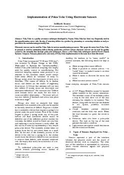
3 : The Design of Everyday Things, by D.A. Norman, 1988, Doubleday Sensors are used to detect defects as early as possible in the manufacturing/assembling process. Proximity sensors are used to check the presence or absence of necessary components or to check the proper orientation of components to be assembled in the assembly line. Pressure sensors are used to check the fluid pressure to be in the required range and LVDTs are used to detect displacement defects. Many other sensors like reed switches, optical sensors are employed according to the sensing needs in Poka - Yoke implementa tion. Figure 1 (a) and (b): The above figures show how optical sensors can be used for mistake - pro ofing. The optical sensor turns on (1(b)) only when it detects the hand of the worker in the washer bin, thus removing the possibility of the worker forgetting to pick up a washer because the machine would not actuate until the optical sensor is switched on by the worker‘s hand. This is an exampl e of how sensors can effectively avoid human error. Sensors are broadly classified into two types depending on whether they require external energy input for functioning or not – Active and Passive. Passive sensors are those for whose functioning we need t o provide an external current or voltage input. The passive sensors used in the assembly plant were – Proximity sensors, pressure switches, photo - electri c sensors, limit switches, Linear Variable Differential Transformers (LVDT) , etc. We keep our focus tow ards 3 - wire sensors, although other types of sensors are available too. In three - wire proximity sensors there are two further classifications based on the type of output the sensors give: NPN proximity sensor and PNP proximity sensor. NPN sensor consists o f a NPN output transistor and is used where the load is connected to the positive terminal of the power source. A PNP sensor consists of PNP output transistor and is used where the load is connected to the negative terminal of the power source. A PNP senso r is called a source sensor and a NPN sensor is called a current sinking sensor. The sensors used in the manufacturing sector for Poka - Yoke work on standard values of input like 5VDC, 12VDC or 24V DC. The PNP sensors gave an output of 24V through the black wire and the NPN sensors gave a zero volt output. The brown and blue wires are positive and negative respectively. Three - wire sensors consist of black, brown and blue wires where black is the output wire, brown and blue are positive and negative respectiv ely. The PNP sensors give a positive output (standard values 5VDC, 12VDC, 24VDC, etc) whereas the NPN sensors give a negative output (zero VDC). Figure 2 : NPN and PNP Sensor Output for 24VDC Input Sensors are also available in Normally Open(N.O.) and Nor mally Closed(N.C.) types. Since the sensors give standard output values (5VDC, 12VDC, etc), this amount of voltage is not enough is not enough to activate a circuit that functions on 250VDC, say. To solve this voltage problem control relays are used to switch on an external circuit of any voltage rating using the 24VDC/0VDC or any other standard values that are obtained from the sensor. A control relay is an electro - mechanical device which activates one or more switches according to the curr ent flowing through a coil not connected to the switches. A relay basically consists of an electromagnet with two possible states such that when sufficient current flows through the coil, the core of the coil attracts a ferromagnetic armature which mechani cally operates switches. A spring is designed to snap the contacts between the two states and so that there should not be a certain value of current at which the contacts remain in an intermediate state. Figure 3: Basic Circuit Diagram for a Control Rela y Correct selection of relays should be made before using them in a particular operation. Considerations like speed of operation, sensitivity and hysteresis should be kept in mind. Typical contact relays operate in the 5ms to 20ms range, but relays with sp eed of operation as fast as 100us (micro - seconds) are also available. Reed relays which are actuated by low currents and switch fast are suitable for controlling small currents. 2.1 Pressure Se
3 nsors/Switches A pressure switch i
nsors/Switches A pressure switch is a form of switch that makes electrical contact when a certain set pressure has been reached on its input. This is used to provide on/off switching from a pneumatic or hydraulic source. The switch may be designed to make contact either on pressure rise or on pressure fall. The pressur e sensor consists of a resistive sensor circuit which obeys Ohm‘s Law and Kirchhoff‘s Rules for circuit analysis. The pressure switch also employs Wheatstone bridge in its functioning. A Wheatstone bridge is used as an improvement to the simple voltage div ider. It consists of a simple voltage divider, combined with a second voltage divider called reference divider. It consists of fixed resistances and is used so as to make a reference voltage that is same as the voltage of the sense voltage divider at some nominal value of sense resistance. The output of the sense divider and the reference divider are the same when the sense resistance is at its starting value. The resistors used in the pressure sensor‘s circuit are piezoresistors i.e. the value of their resistance changes with the application of pressure. Changes in the sense resistance lead to creation of a differential voltage. A differential amplifier is used to produce the difference between the two voltages and amplify the re sult. 4 Digital pressure switches are also widely applied for pressure sensing operations. These are micro - processor based and consist of various modes like hysteresis mode and window comparator mode, they also have the provisions to store the pressure dat a and copy the desired pressure settings into other pressure switches. These have very easy operation and can be operated even by semi - skilled labour. 2.2 P roximity Sensors These are the type of sensors that detect objects without physical contact with the objects that are lying in proximity to the sensors. The working principle of these involves a high frequency oscillator that creates field in close surroundings of the sensing surface. The presence of object changes the output state of the sensor and thus the object is sensed according to the change in the output state. The operating distance of the sensors depends on the actuators‘ shape and size and strictly linked to the nature of material of the object. These have great use in applications where small d efects (in order of a few millimetres ) have to be measured. Figure 5 : Proximity Sensor Configuration Features of proximity sensors are: 4 Wilson, Jon S. ( 2005 ) . Sensor Technology Handbook. pp 6 - 7 1. Non - contact detection, eliminating damage to sensor head and target. 2. Long service life due to non - contact output. 3. Stable detection even in harsh environments exposed to water or oil splash. 4. High response speed. Proximity sensors are basically of four types: Inductive Capacitive Magnetic Photoelectric Table I 5 Targets and Range of Various Sensors SENSOR TARGET RANGE Limit Switch Any 0 (Contact Required) Reed Switch Magnetic Materials 20 mm Photo - electric Opaque Materials 0.1m – 50 m Also Depends on Shape of target Inductive Conducting Materials Ferrous: 50mm Non Ferrous: less than 50mm Capacitive Most solids and liquids 30mm Ultrasonic Non - porous large objects 30mm – 10m 2.2.1 Inductive Proximity Sensors Inductive proximity sensors consist of a coil and an oscillator that creates an electromagnetic field in close surroundings of the sensing surface. The presence of me tallic object (actuator) in the operating area causes a dampening of the oscillation amplitude. T he rise or fall of such oscillation is identified by a threshold circuit that changes the output of the sensor. These are based on the principles of eddy curre nts and are used for metallic objects or other conducting objects in which eddy currents can be induced. These sensors make use of inductance measurement circuits 6 to measure the changes in inductance in the operating area.
4
2.2.2 Capacitive Proximity Sensors Capacitive p roximity sensors used for detection of non - metallic objects (liquid, plastic, wooden materials and so on). Capacitive proximity sensors use the variation of capacitance between the sensor and the object being detected. The main difference 5 Industrial Automation by D.W. Pessen, Wiley Interscience between inductive and capacitive proximity sensors is that capacitive type proximity sensors create an electrostatic field near the sensing surface, not electromagnetic field as in case of induction type sensors. Capacitance measuring circuits 6 are employed for measuring c hanges in capacitance in the operating area. The sensing surface of a capacitive sensor is formed by two concentrically shaped metal electrodes of an unwound capacitor. When an object nears the sensing surface it enters the electrostatic field of the elect rodes and changes the capacitance in an oscillator circuit. As a result, the oscillator begins oscillating. The trigger circuit reads the oscillator‘s amplitude and when it reaches a specific level the output state of the sensor changes. As the target move s away from the sensor the oscillator‘s amplitude decreases, switching the sensor output back to its original state. 2.3 Magnetic Proximity Sensor Magnetic (Reed Switch ) proximity sensor is actuated by permanent magnets. Operating principle is based on the use of reed contacts whose thin plates are hermetically sealed in a glass bulb with inert gas. The presence of magnetic field makes the thin plates flex and touch each other causing an electrical contact. The plate surface has been treated with special mater ial particularly suitable for low current or high inductive currents. 2.4 Photoelectric Sensors Photoelectric sensors based on the principle of reflection of optical beams. These consist of an emitter and a receiver for sensing purposes. The emitter emits the optical beam, and the change in density received at the receiver, due to the obstruction in the beam‘s path by the object, is used to detect the distance or other characteristics of the object. 3. Case Study The following example shows how a panel for Poka – yoke using electronic sensors was designed and implemented on a rivetin g machine in the drum brake house of Bosch Chassis Systems, Gurgaon Plant. Figure 6 : The Riveting Machine at Bosch Chassis Systems, Manesar Plant . Reed switches check the correct bend in the handbrake lever. 6 Wilson, Jon S. (2005). Sensor Technology Handbook. p 8. T he above pictures show the rive ting machine. The circuit shown in the diagram below is used to check any defect in the hook bend of the han d brake lever and prevent riveting of a defective part, thus preventing a defective part reaching the customer.The reed switch is attached to a pneumatic cylinder. The reed switch turns on only when the width gauge that is mechanically coupled with the pneumatic cylinder completely enters the hook, thus detecting the presence of correct hook bend of the lever. If incorrect bend is there then the width gauge would be obstructed by the wrong size of the hook and cylinder would not switch on the reed switch. Furthe r, on - delay and off - delay timers are used to control the operation of the machine automatically and this prevents any error or mistake that could have been made by the machine‘s operator. Timers that are used are : ON - DELAY TIMER - This type of timer dela ys the switching on of the circuit when the coil is energized. When the coil is de - energized the circuit switches off immediately without any delay. OFF - DELAY TIMER: This is the type of timer in which the circuit switches on immediately when the coil is en ergized, but when the coil is de - energized, it delays the switching off of the circuit according to the time set by the operator. Figure 6 : The above panel was setup on the riveting machine in the drum brake house. Reed switch (magnetic
5 sensor) and timers were employed for and timers were employed for")
sensor) and timers were employed for P oka - Y oke. When the reed switch senses the presence of the correct model of component on the riveting machine, TR1 is turned on, which delays the switching on of the main punch cylinder (riveting) by 10 seconds and stays turned on for 20 seconds. TR2, which is an off delay timer also gets activated simultaneously with TR1. TR2 delays the turning off of the lever profile checking cylinder circuit by 30 seconds.So , when TR1 is turned on, the main punch cylinder gets actuated after a 10 second delay and turns off after another 10 seconds. After ten more seconds (total of 30 seconds), TR2 switches the lever profile checking cylinder circuit off and the operation of the riveting machine gets completed successfully and both cylinders return to their normal position. Figure 7 : Left: The hook on the handbrake lever is sensed by the reed switch Right: The lever profile checking cylinder in the riveting machine. This way poka - yoke can be implemented to reduce the scope for human mistakes by making use of sensors. When this poka - yoke was not present on this machine, a defect of hook bend was reported by Maruti Suzuki India Ltd., Gurgaon which is a cutsomer of Bosch Chassis Systems on 25 May, 2011 when they received a defective part. Implementation of this poka - yoke prevents this situation from occuring when a defect in a particular part is reported by the customer itself in which case the customer demands the supplier to test all other parts for defects. This requires a lot of effort and often adversely disturbs the production of the manufacturing plant. So, by employing a simple technique during assembly a lot of effort, mo ney and time is saved. Another addition that was made to the riveting machine was that a proximity switch was provided in the circuit, before the ‗start‘ push - button. The proximity switch was so installed that it only switched on when there was a componen t kept on the machine. This ensured that the machine did not run if the worker forgot to keep the component on the machine. This also made the machine‘s functioning safer for the operator. 4. Conclusion Thus Electronic Sensors can be used for effective mistak e – proofing in manufacturing plants and can drastically reduce the rejection rate of production thereby reducing the cost of production and enhancing customer satisfaction and confidence. 5. Acknowledgment The author would like to thank Mr. Brijesh Singh, Maintenance Department, Bosch Chassis Systems, Gurgaon Plant . He continually maintained a level of excitement in his teachings and all involvements in this projec t. Further a cknowledgment to Mr. Rajat Tandon , Plant Manager, Bosch Chassis Systems, G urgaon Plant for taking keen interest in the project and providing vital lab oratory and infrastructure facilities that have given this paper a certain level of practical outlook . 6. References [1] Fraden, J. (2004). Handbook of Modern Sensors: Physics, Designs and Applications (3rd Edition ed.). New York : AIP Press, Springer - Verlag, Inc. pp. 1 - 119. [2] ― A Tutorial on Mistake - Proofing ‖ with Brian T. Downs. The Quality Yearbook , Woods, J. and Cortada, J. Eds. New York: McGraw - Hill, 1999, pp. 410 - 418. [3] Shigeo Shingo. Zero Quality Control: Source Inspection and the Poka - yoke System. Productivity Press. p 45. [4] Shigeo Shingo. The Sayings of Shigeo Shingo: Key Strategies for Plant Improvement. Productivity Press. p 145. [5] Bandyopadhyay, J.K. Poka Yokay Systems to Ensure Zero Defect Quality Manufacturing. International Journal of Management Vol. 10. 1993. pp 28 - 33. [6] Zocholl, Stan (2003). AC Motor Protection . Schweitzer Engineering Laboratories, Inc.. ISBN 0972502610, 978 - 0972502610. [7] Norwestern University, Mechanical Engineering Department. ―Piezoresistive Sensors‖. 25 Jul 2005. 27 Jun 2011. http://www.mech.northwestern.edu/FOM/LiuCh06v3_072 505.pdf [8] Siemens Technical Education Program. ―Capacitive Proximity Sensors Theory of Operation ‖. 1 Feb 2002. 2 Jul 2011. http://www.automationmedia.com/Port1050%5CSiemensF reeCourses%5Csnrs_3.pdf [9] Wilson, Jon S. (2005). Sensor Technology Handbook. Newnes. ISBN: 0 - 7506 - 7729 - 5 . pp 6 -