
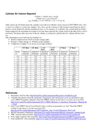
INTRODUCTION TO PNUEMATIC SYSTEM Pneumatic technology deals with the study of behavior and applications of compressed air in our daily life in general and manufacturing automation in particular ID: 1030667
Download Presentation The PPT/PDF document "Pneumatics Prof. V. S. Chavan" is the property of its rightful owner. Permission is granted to download and print the materials on this web site for personal, non-commercial use only, and to display it on your personal computer provided you do not modify the materials and that you retain all copyright notices contained in the materials. By downloading content from our website, you accept the terms of this agreement.


1. PneumaticsProf. V. S. Chavan
2. INTRODUCTION TO PNUEMATIC SYSTEMPneumatic technology deals with the study of behavior and applications of compressed air in our daily life in general and manufacturing automation in particular. Pneumatic systems use air as the medium which is abundantly available and can be exhausted into the atmosphere after completion of the assigned task.The technology of pneumatics was much used in industry before the beginning of the Second World War (1939-44). The reason for using pneumatics, or any other type of energy transmission on a machine, is to perform work.
3. Pneumatic systemsPneumatic systems similar to hydraulic systemsUse compressed air as working fluid rather than hydraulic liquid70psi - 150psi, much lower than hydraulic system pressures, much lower forces than hydraulic actuatorsEnergy can be stored in high pressure tanksOpen systems, always processing new air
4. Advantages of Pneumatic systemHigh effectivenessHigh durability and reliabilitySimple designHigh adaptability to harsh environmentSafetyEasy selection of speed and pressureEnvironmental friendlyEconomical
5. Limitations of Pneumatic systemRelatively low accuracyLow loadingProcessing required before useUneven moving speedNoise
6. Basic Components of Pneumatic System
7. a) Air filters: These are used to filter out the contaminants from the air. b) Compressor: Compressed air is generated by using air compressors. Air compressors are either diesel or electrically operated. Based on the requirement of compressed air, suitable capacity compressors may be used. c) Air cooler: During compression operation, air temperature increases. Therefore coolers are used to reduce the temperature of the compressed air. d) Dryer: The water vapor or moisture in the air is separated from the air by using a dryer. e) Control Valves: Control valves are used to regulate, control and monitor for control of direction flow, pressure etc.
8. f) Air Actuator: Air cylinders and motors are used to obtain the required movements of mechanical elements of pneumatic system.g) Electric Motor: Transforms electrical energy into mechanical energy. It is used to drive the compressor. h) Receiver tank: The compressed air coming from the compressor is stored in the air receiver.
9. Air filter and water trap Air filter and water trap is used to, • prevent any solid contaminants from entering in the system. • condense and remove water vapor that is present in the compressed air.
10. Compressor: It is a mechanical device which converts mechanical energy into fluid energy. The compressor increases the air pressure by reducing its volume which also increases the temperature of the compressed air. The compressor is selected based on the pressure it needs to operate and the delivery volume.Positive displacement compressors include piston type, vane type, diaphragm type and screw type.Piston type compressor
11. Receiver tank :The air is compressed slowly in the compressor.But since the pneumatic system needs continuous supply of air, this compressed air has to be stored.The compressed air is stored in an air receiver as shown in Figure The air receiver smoothens the pulsating flow from the compressor. Also the large surface area of the receiver helps in dissipating the heat from the compressed air. The air receiver should be large enough to hold all the air delivered by the compressor.
12. Generally the size of receiver depends onDelivery volume of compressor. • Air consumption. • Pipeline network • Type and nature of on-off regulation • Permissible pressure difference in the pipelines
13. Types of ValvesType: Spool, poppet, ball, butterfly valves, etc.Check valve (One directional flow)Poppet valveSpool valveBall valveButterfly valve
14. Valve symbolsControl methodsValve connectionsValves with controls indicatedPosition with texts indicates initial position
15. Actuators Actuators are output devices which convert energy from pressurized hydraulic oil or compressed air into the required type of action or motion. In general, hydraulic or pneumatic systems are used for gripping and/or moving operations in industry. Actuators can be classified into three types. 1. Linear actuators: These devices convert pneumatic energy into linear motion. 2. Rotary actuators: These devices convert pneumatic energy into rotary motion. 3. Actuators to operate flow control valves: these are used to control the flow and pressure of fluids such as gases, steam or liquid.
16. 16What can Pneumatics do? Operation of system valves for air, water or chemicals Operation of heavy or hot doors Unloading of hoppers in building, steel making, mining and chemical industries Ramming and tamping in concrete and asphalt laying Lifting and moving in slab molding machines Crop spraying and operation of other tractor equipment Spray painting Holding and moving in wood working and furniture making Holding in jigs and fixtures in assembly machinery and machine tools Holding for gluing, heat sealing or welding plastics Holding for brazing or welding Forming operations of bending, drawing and flattening Spot welding machines Riveting Operation of guillotine blades Bottling and filling machines Wood working machinery drives and feeds Test rigs Machine tool, work or tool feeding Component and material conveyor transfer Pneumatic robots Auto gauging Air separation and vacuum lifting of thin sheets Dental drills and so much more… new applications are developed daily
17. 17Properties of compressed airAvailabilityStorageSimplicity of design and controlChoice of movementEconomy
18. 18Properties of compressed airReliabilityResistance to EnvironmentEnvironmentally clean.Safety
19. 19What is Air?In a typical cubic foot of air --- there are over 3,000,000 particles of dust, dirt, pollen, and other contaminants.Industrial air may be 3 times (or more) more polluted.The weight of aone square inchcolumn of air(from sea levelto the outer atmosphere,@ 680 F, & 36% RH)is 14.69 pounds.
20. 20Air Treatment
21. 21Compressing AirOne cubic foot of air7.8 cubic feet of free airOne cubic foot of100 psig compressed air(at Standard conditions) with 7.8 times the moisture and dirtcompressorCFM vs SCFMpsig + 1 atm1 atmCompressionratio=Compressed air is always related at Standard conditions.
22. 22Relative HumidityCompressor 1 ft3 @100 psig1950 F 100% RH57.1grams of H20 1 ft3 @100 psig 770 F 100% RH.73grams of H20 1 ft3 @100 psig -200 F 100% RH.01grams of H20 1 ft3 @100 psig 770 F 0.15% RH.01grams of H2056.37grams of H20.72grams of H20Adsorbtion DryerCompressorExitReservoir TankAirline Drop
23. 23Air MainsRing MainDead-End Main
24. 24PressureIt should be noted that the SI unit of pressure is the Pascal (Pa) 1 Pa = 1 N/m2 (Newton per square meter)This unit is extremely small and so, to avoid huge numbers in practice, an agreement has been made to use the bar as a unit of 100,000 Pa.100,000 Pa = 100 kPa = 1 barAtmospheric Pressure=14.696 psi =1.01325 bar =1.03323 kgf/cm2.
25. 25Isothermic change (Boyle’s Law)with constant temperature, the pressure of a given mass of gas is inversely proportional to its volumeP1 x V1 = P2 x V2P2 = P1 x V1 V2V2 = P1 x V1 P2Example P2 = ?P1 = Pa (1.013bar)V1 = 1m³V2 = .5m³P2 = 1.013 x 1 .5= 2.026 bar
26. 26Isobaric change (Charles Law)…at constant pressure, a given mass of gas increases in volume by 1 of its volume for every degree C in temperature rise. 273 V1 = T1 V2 T2V2 = V1 x T2 T1T2 = T1 x V2 V1Example V2 = ?V1 = 2m³T1 = 273°K (0°C)T2 = 303°K (30°C)V2 = 2 x 303 273= 2.219m³10
27. 27Isochoric change Law of Gay Lussac at constant volume, the pressure is proportional to the temperature P1 x P2 T1 x T2P2 = P1 x T2 T1T2 = T1 x P2 P1 Example P2 = ?P1 = 4barT1 = 273°K (O°C)T2 = 298°K (25°C)P2 = 4 x 298 273= 4.366bar
28. Pneumatic ActuatorsFor power, motion and control
29. IntroductionPneumatic actuators include linear cylinders and rotary actuators. They are devices providing power and motion to automated systems, machines and processes.A pneumatic cylinder is a simple, low cost, easy to install device that is ideal for producing powerful linear movement.Speed can be adjusted over a wide range.A cylinder can be stalled without damage.
30. IntroductionAdverse conditions can be easily tolerated such as high humidity, dry and dusty environments and cleaning down with a hose.The bore of a cylinder determines the maximum force that it can exert.The stroke of a cylinder determines the maximum linear movement that it can produce.The maximum working pressure depends on the cylinder design. School cylinders work up to 9 bar.Thrust is controllable through a pressure regulator.
31. Basic Construction 1 cushion seal 2 magnet 3 cushion sleeve 4 barrel 5 guide bush 6 rod and wiper seal 7 front end cover 8 front port 9 reed switch10 piston rod11 wear ring12 piston seal13 rear end cover14 cushion screw
32. Fundamental designs
33. Fundamental designsPneumatic actuators are made in a wide variety of sizes, styles and types including the following Single acting with and without spring returnDouble actingNon cushioned and fixed cushionedAdjustable cushionedMagneticRodlessRotaryClampingBellows
34. Single acting spring returnSingle acting cylinders have a power stroke in one direction onlyNormally inNormally outClick the illustrations to start and stop animation
35. Double actingDouble acting cylinders use compressed air to power both the outstroke and instroke.Superior speed control is possibleThere areNon-cushioned typesFixed cushioned typesAdjustable cushioned types
36. Double acting non-cushionedNon cushioned cylinders are suitable for full stroke working at slow speed.Higher speeds with external cushionsClick the illustration to start and stop animation
37. Force
38. Cylinder sizing for thrustThe theoretical thrust (outstroke) or pull (instroke) of a cylinder is calculated by multiplying the effective area of the piston by the working pressure. The effective area for thrust is the full area of the cylinder bore “D”. The effective area for pull is reduced by the cross section area of the piston rod diameter “d”.d D
39. Cylinder sizing for thrustIn the formula, P is divided by 10 to convert bar to Newtons per square millimetre (1 bar = 0.1 N/mm2)WhereD = Cylinder bore in millimetresP = Pressure in barF = Thrust or Pull in NewtonsThrustF=D24P10Newtons
40. Cylinder sizing for thrustPulling force F will be less than the thrust due to the area lost to the piston rodWhereD = Cylinder bore in millimetresd = Piston rod diameter in millimetresP = Pressure in barF = Thrust or Pull in NewtonsPullF=(D2-d2)P40Newtons
41. Speed control
42. Speed controlThe maximum natural speed of a cylinder is determined by:the cylinder size,the ports size, inlet and exhaust valve flow, the air pressure, the bore and length of the hoses, the load against which the cylinder is working.
43. Speed controlFrom the natural speed it is possible to increase or reduce it.Normally a smaller valve reduces cylinder speed.A larger valve might increase cylinder speed.A limiting factor will be the aperture in the cylinder portsrestricted apertureunrestricted aperture
44. Speed controlOnce a valve, cylinder, pressure and load are selected, adjustable speed control is effected with flow regulators.Speed is regulated by controlling the flow of air to exhaustThe front port regulator controls the outstroke speed and the rear port regulator controls the instroke speed.
45. Flow regulatorUni-directional, line mounted adjustable flow regulator Free flow in one directionAdjustable restricted flow in the other direction
46. Banjo flow regulatorDesigned to fit directly in to the cylinder port, so placing adjustment at the appropriate cylinder end. Select the type to give conventional flow restriction out of the cylinder and free flow in.
47. Increasing speedIn some applications cylinder speed can be increased by 50% when using a quick exhaust valve.When operated, air from the front of the cylinder exhausts directly through the quick exhaust valve. Built in cushioning will be less effective.
48. Quick exhaust valveAir flows from the control valve in to the cylinder past a poppet lip seal.When the control valve is operated the falling pressure from the valve allows the poppet seal to snap open.The air in the cylinder rapidly exhausts through the large exhaust port and silencer. 1 2 1 2 12
49. 49Flow Amplification
50. 50Signal Inversion
51. 51Selection
52. 52Memory Function
53. 53Delayed switching on
54. 54Delayed switching off
55. 55Pulse on switching on
56. 56Pulse on releasing a valve
57. 57Direct Operation and Speed Control
58. 58Control from two points: OR Function
59. 59Safety interlock: AND Function
60. 60Safety interlock: AND Function132
61. 61Inverse Operation: NOT Function
62. 62Direct Control
63. 63Holding the end positions
64. 64Semi Automatic return of a cylinder
65. 65Repeating Strokes
66. 66Sequence Control
67. 67
68. 68
69. 69
70. 70
71. 71
72. 72
73. 73
74. Introduction to Pneumatic ComponentsBicycle PumpEnergy TransformationStorage Reservoir Energy Storage3 Way Shut Off ValveEnergy ControlRegulatorEnergy ControlSolenoid ValveEnergy ControlPneumatic Cylinder or Linear ActuatorEnergy TransformationOrder of Air Flow
75. Pump HandlePump Tube or CylinderPressure GaugeFill ValveWith Locking LeverFoot StandPiston RodPistonBicycle PumpConverts Mechanical Energy into the Potential Energy of Pressurized AirCharges the Pneumatic Battery
76. Pneumatic ReservoirSchrader Valve Connects to PumpMounting Nuts (2)One Touch Quick Connect FittingConnects to 3 Way ValveAir Storage Capacity is a Function ofPressure x Volume = CapacityEnergy Stored as Compressed Air
77. 3 Way ValveFinger KnobShown in Off PositionOutlet PortTo RegulatorInlet PortFrom ReservoirDirection Arrow On Valve BodyThree Operational States or ModesOFF – Vent – On
78. The RegulatorPressure Adjusting Knob *Pull out before turning *Push in to lock *Turn Clockwise to Raise Pressure.Pressure Gauge0-150 psi0-1 MPaAir Flow Directional ArrowLower Pressure SettingsMeans Less Air ConsumptionHigh Pressure Inlet Controlled Pressure Side
79. The Regulator continued
80. The Regulator continuedNote: Be certain toverify the direction of air flow through the regulator.The incoming air (from The 3 Way Valve) Enters the port marked with an arrow.
81. 3/2 Solenoid ValveSolenoid WiresExhaust Port “E”Pressure Port “P1”From RegulatorActuator Port “A2”Valve Body
82. The Pneumatic Cylinder or Linear ActuatorSpeed ValvePiston and RodClevisOne Touch Quick Connect FittingCylinder BodyPneumatic Mounting BracketCylinder Force = Pressure x Piston Area
83. One Touch Quick Connectors
84. Pneumatic Component ConnectionsBuild ItTest ItUse It
85. After Building and Testing the Pneumatic CircuitDetermine These Performance CharacteristicsHow many times will the pneumatic cylinder cycle at 50 psi when the reservoir is charged to 150 psi?What is the theoretical force of the piston at 50 psi?What is the actual force of the piston at 50 psi?What is the speed of the piston in inches per second at 50 psi? Does pressure affect speed and if so, can you measure and graph the relationship?Which answers can be found mathematically?Which should be measured directly?
86. Air Compressors
87. Pneumatics: A system which uses compressed air is called pneumatics.It deals with the study of behaviour & application of compressed airA basic pneumatic system consist of a source of compressed air, control valves, pipelines & pipe fittings and pneumatic accessories like filter, regulator and lubricatorAir compressor
88. For operating pneumatic tools such as drills, screw drivers, hammers, chiesselsFor pneumatic cranesFor pneumatic brakes of automobiles, railways and pressesFor agricultural accessories such as dusters and sprayersApplication of compressed air
89. For drive of CNC machine toolsFor pneumatic conveying of materialsFor pneumatic gauging, inspection and low cost automation systemsApplication of compressed air
90. An air compressor is a mechanical device that increases the pressure of air by reducing volume.Air is compressible, the compressor reduces the volume of air and induces pressure in the airAn air compressor converts electrical energy into kinetic energy in the form of the airIntroduction to compressors
91. The compressed air is stored in the air receiver and can be used for cleaning under pressure, generating torque and develop force using actuatorsThis source is free of cost, safe, flexible and convenientAir compressor has very few parts hence maintenance is very lowIntroduction to compressors
92. Air compressors are classified according to method of energy transfer and pressure generation i.e. positive displacement and dynamic compressorsPositive displacement compressors work on the principle of increasing the pressure of air by reducing the volume of air in an enclosed chamberClassification of air compressor
93. Dynamic compressors works on the principle of imparting the energy by rotating vanes of impeller on air flowing through casing that increases pressure in airClassification of air compressor
94. Classification of air compressor
95. According to number of stagesSingle stage, double stage, three stage of multiple stageAccording to actionSingle acting or double actingAccording to position of cylinder w.r.t. crankshaftCylinders inline, vertical, radial position, V-type cylinder arrangementClassification of air compressor
96. According to prime moverElectric motor drive or IC engine drive, Gas turbine drivesAccording to cooling mediumAir cooled, water cooled air compressorsClassification of air compressor
97. Reciprocating Air compressors
98. Reciprocating air compressors are positive displacement type of air compressors.These are piston & diaphragm type, vane type, gear type, screw type compressors.Reciprocating Air compressors
99. The principle of operation is same but according to stages the delivery pressure is different in each compressor.Reciprocating Air compressors
100. A reciprocating air compressor consist of a piston which is enclosed within a cylinder and equipped with suction and discharge valveThe piston receives power from electric motor or IC engine. Reciprocating Air compressors
101. The compression of air is done by first drawing a volume of air into the cylinder through suction valve during suction stroke of piston and then compressed and discharged through delivery valve during delivery strokeReciprocating Air compressors
102. In this type the entire compression is carried out in a single cylinderSingle stage Reciprocating Air compressors
103. Single stage reciprocating air compressor
104. When piston starts moving downwards, the pressure inside the cylinder falls below atmospheric pressure that opens suction valve.The pressure of the air in the cylinder rises during compression and at the end of compression, delivery valve opens and discharges the compressed air into the receiver tank.Single stage Reciprocating Air compressors
105. Single stage air compressor develop pressure upto 7 bar.For higher pressures multistage compressors are suitableSingle stage Reciprocating Air compressors
106. It consist of two cylinders – low pressure cylinder and high pressure cylinderPiston, crankcase, piston rod, crank, crankshaft, oil, fins etc.Double stage Reciprocating Air compressors
107. Double stage reciprocating air compressor
108. The fresh air is drawn inside the L.P. cylinder through inlet suction filter.This air is compressed by piston As the piston moves towards the end of cylinder, the air compression took place.Double stage Reciprocating Air compressors
109. The delivery valve opens and this compressed air from L.P. cylinder is directed to enter inside the high pressure cylinder.In high pressure cylinder this pressurised air is further compressed to higher pressure.Double stage Reciprocating Air compressors
110. The high pressure air from H.P. cylinder is then delivered to receiver through discharge valves.In this compressor, a pressure of air delivered is upto 13 bar. Double stage Reciprocating Air compressors
111. Simple in designLower initial costEasy to installHigher effeiciencyAdvantages
112. Number of moving parts are moreHigher maintenance costHeavy foundation is required as it has vibration problemCannot run at full capacityDisadvantages
113. Rotary vane compressor
114. It is positive displacement type compressor.It provides higher efficiency and flow rates over a wide range of pressureRotary vane compressor consist of rotor with a number of vanes inserted in the radial slots cut in rotor.Rotary vane compressor
115. The rotor is mounted eccentric in a casing. The vanes slides radially in and out of the rotor.As the rotor rotates at higher speed, centrifugal force throws the vanes outward keeping the end of vane in contact with the stator ring.Rotary vane compressor
116. As the rotor turns, compression is achieved as the volume goes from a maximum at intake port to minimum at the exhaust port.An oil is injected into the air intake and along the stator walls to cool the air and lubricate bearing and vanes and to provide a seal between the vane and stator wall to reduce internal leakage.Rotary vane compressor
117. Simple designCompact in sizeLight in weightEasy to installLow costLow maintenance costLonger lifeFew moving partsLow rotational speed Expensive foundation not requiredAdvantages:
118. Lower efficiencyDifficulty with higher pressure above 200 psiOil injected designs have oil carryoverDisadvantages:
119. Vane type rotary compressor
120.
121. It is dynamic compressor.It consist of a rotating impeller which rotates at higher speed (upto 60000 rpm)An impeller fitted inside casing force the air to the rim of impeller, increasing velocity of air.Centrifugal compressor
122. Centrifugal compressor
123. Centrifugal Supercharger
124. A diffuser (divergent shape of casing) section converts the velocity of air to cause an increase in pressure. This process is called dynamic compression.These compressors are used for continuous, stationary services in industries like oil refineries, chemical and petrochemical plants, natural gas processing plants.Centrifugal compressor
125. These are also used in IC engine superchargers and turbochargers.In gas turbine plantsIt can provide extremely high output pressures greater than 10000psi.Centrifugal compressor
126. It consist of two screws - one with convex and the other with concave contour mostly called male and female rotor respectively.These two screws gets rotating by means of gear trips there by sucking the air through an inlet port in chamber and then compressing the sameScrew compressor
127. Screw compressor
128. The helix of the male and female rotor screw is designed to permit complete charging of the inter lobe space before the re-mesh.On completion of the filling operation the inlet end of male and female lobes begins to re-engage thus reduces the volume of air continuously.Screw compressor
129. Screw Compressor
130. Thus compression begins and air is discharged at the end of other side.There is no contact between male and female rotors and casing. Hence no lubrication require but oil may injected for the purpose of cooling.Screw compressor
131. Details of Screw Compressor
132. Details of Screw Compressor
133. It is used in applications where higher flow at comparatively low pressure is required.Twin lobe compressor
134. Here two lobes are placed in a casing The air is transferred from suction side to the delivery side with continuous rotation of two lobesThe lobes are precisely maintained and the casing also maintained to close tolerancesIt has limited compression ratio @ 1.7Twin lobe compressor
135.
136. Multi stage compressor is use to develop pressures more than 35 kg/cm2. For preparation of mineral water bottle, air pressure more than 40 kg/cm2 is required to produce desired shape of bottle at bottom side.Here two stage compressor is not used as it produces pressure up to 35 kg/cm2 .Three stage compressor is use as it produces pressure up to 85 kg/cm2 .Above four stage compressor is used.Multistage compressor
137. The working is same as that of double stage compressor.In three stage compressor fresh air from atmosphere enters first stage cylinder through air cleaner.Here it is compressed by piston to 4 kg/cm2 and then delivered to second stage cylinder through intercooler for further compression.Multistage compressor
138. In second stage cylinder low pressure air is compressed upto 14 kg/cm2 and discharge to third stage cylinder through second intercooler to increase air pressure up to desired delivery pressure i.e. 35 to 85 kg/cm2Multistage compressor
139. Selection of air compressor for given application is governed by several factors as belowPressureFlow rates or capacityGeometry of cylinderSpeed of pistonThe layout of pipe line, system requirement and the distance of user machine from compressor plant Selection of compressors
140. Pressure :The discharge pressure from the compressor should be decided first considering the needs of the cylinder, air motor & pressure drop in the circuit.Most of pneumatic systems and tools are designed for pressure of 6 – 7 bar.A compressor used should meet the requirement.Selection of compressors
141. Pressure :Pneumatic circuit requiring air at high pressure can be supplied with air by a separate high pressure compressor While any low pressure can be met by availing a reducing valve.For huge air flow rates at pressures below 2 bar, a turbo-blower or low pressure rotary compressor may be used.Selection of compressors
142. Flow rates or capacity:-Volume of air required per minute is also an important factor for selection.The capacity should be adequate enough to supply air to all devices operating simultaneously.In many plants where pneumatic tools are operated intermittently, in such cases maximum instantaneous demand of the compressed air has to be find first.Selection of compressors
143. Geometry of cylinder:-For single cylinder geometric fashion :- vertical-single acting or double acting horizontal- single or double actingFor two cylinders geometric fashion:- - vertical inline, single or double acting - V-type, single or double acting - horizontal duplex, double actingSelection of compressors
144. Speed of piston:-The speed of piston inside the cylinder must also be considered.For small capacity compressor, the piston speed 300 m/min, whereas for large capacity compressor piston speed 250 m/min.The layout of pipe line, system requirement and the distance of user machine from compressor plant Selection of compressors