

Brightness Limiting Phenomena Simulated bunch profile for 20pC and 80pC bunch charges from a realistic birefringent pulsestacked laser profile The onset of the virtual cathode instability VCI ID: 721524
Download Presentation The PPT/PDF document "High Brightness Electron Source Develop..." is the property of its rightful owner. Permission is granted to download and print the materials on this web site for personal, non-commercial use only, and to display it on your personal computer provided you do not modify the materials and that you retain all copyright notices contained in the materials. By downloading content from our website, you accept the terms of this agreement.


Slide1
High Brightness Electron Source Development
Brightness Limiting Phenomena
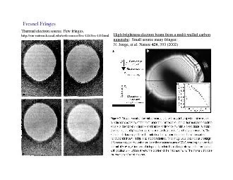
Simulated bunch profile for 20pC and 80pC bunch charges from a realistic
birefringent
pulse-stacked laser profile. The onset of the virtual cathode instability (VCI) is apparent in the bunch lengthening and breakup.
MK II DC Gun: Pushing brightness limits
A new
DC
photogun
is under construction @ Cornell. It will feature:A segmented, shielded HV ceramic to reach higher voltage regimes. Adjustable cathode-anode gap, to allow precision control of the photocathode field, on which the onset of the VCI depends.A genetically optimized electrode profile to provide highest brightness, subject to empirical breakdown voltage constraints.
A 6-D phase space measurement beamline, transverse emittance measurement, and ps-resolution deflecting cavity.
Achieving Optimal Brightness
Genetically
optimized 3D laser pulse profile
to minimize space charge induced
emittance growth.
The MK II Gun will employ adaptive 3D laser pulse shaping to allow online optimization of emittance.Temporal shaping via birefringent crystal stackingTransverse – via truncated GaussianGood light transmission, < 20% emittance change from the optimum
Photocathode development
Gun development
CsK2Sb photocathode development
Sub-thermal
emittance
from
GaAs
cathodes
I.V.
Bazarov
, L.
Cultrera
, S. Karkare,
J. Maxson (for the ERL
injector team
)Presented at DOE Contractors’ Mtg, Annapolis, MD, August 22-23, 2011
Multi-Alkali Cathode Prep-chamber with vacuum suitcase
20mA, 8hr run
Crater Light gray
~1.5 mm diameter
Brown colored area
~4 mm diameter
Photocathode film
~0.5
mm
gap
Damage on Si substrate after 20mA run
SEM image of central damaged area
Photocathode Diagnostics
DIAGNOSTIC TECHNIQUES
A
uger Spectroscopy
LEED
Photoreflectance
Electron Energy Analyzers
Response time measurements
Work function measurement
XRF
….
PREPARATION CHAMBERS
GaAs
(
Cs,F
)
Alkali-Antimonide
ERL INJECTOR
DC GUN
In Vacuum Connection
In Vacuum Connection
In Vacuum Connection
In progress…
Supported by DOE DE-SC0003965, NSF DMR-0807731
Use of Genetic Algorithms to optimize gun geometry
Varying Pierce angle (0 to 45
)
Varying gap (2 to 12 cm)