
01576011 1 of 7 Step 1 Connect the KPC1 cable to the KUSB Step 2 Plug the USB Connector of the KUSB to any available USB port on the Step 3 Plug the one end of the KPC1 into the KUSB and th ID: 871155
Download Pdf The PPT/PDF document "Keri USBA Connection and Configuration" is the property of its rightful owner. Permission is granted to download and print the materials on this web site for personal, non-commercial use only, and to display it on your personal computer provided you do not modify the materials and that you retain all copyright notices contained in the materials. By downloading content from our website, you accept the terms of this agreement.


1 Keri USB-A Connection and Configuration
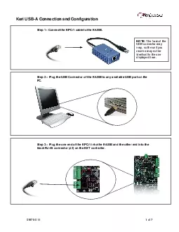
Keri USB-A Connection and Configuration 01576-011 1 of 7 Step 1 - Connect the KPC-1 cable to the K-USB. Step 2 Plug the USB Connector of the K-USB to any available USB port on the Step 3 Plug the one end of the KPC-1 into the K-USB and the other end into the black RJ-45 connector (J2) on the NXT controller. : The form of the USB converter may vary, so the unit you displayed here. Keri USB-A Connection and Configuration 01576-011 2 of 7 Step 4 Connecting the Access Control Hardware Use the Diagram below and the appropriate hardware Installation Guides to hook up the remaining hardware. Keri USB-A Connection and Configuration 01576-011 3 of 7 Step 5 Software Installation Driver Installation - Insert the Installation CD, packaged with the K-USB device, into your computers CD-ROM driv
2 e. The computers operating system auto
e. The computers operating system automatically detects the Adapter and asks you how to begin the driver installation. For Windows XP, select Install the software automatically. For Windows Vista or 7, select Locate and install driver software. NOTE: If the operating system does not auto detect the USB to Ethernet adapter and install its driver, you must manually install the driver using the CD provided with the device. Doors.NET installation NOTE: Doors.NET utilizes the latest Microsoft .NET framework and service patches. Depending on the computer, Windows Update may need to be run multiple times before installing Doors.NET. The installer will install the required .NET patches if needed. Computers that are not up toClose all running applications. Select a Typical Installation to instal
3 l the Doors.NET Application Server, NXT
l the Doors.NET Application Server, NXT Gateway, Administrative Client and the Global Linkage Service. Use the Custom installation Option if different components need to be installed.Step 6 Software Configuration After installation, run the Eclipse License Manger. ( Programs Door. NET License In the Installed Components section, select Application Server under Services Enter the License Keys for the Application Server if one has been provided and click on Activate. Keri USB-A Connection and Configuration 01576-011 4 of 7 If a License Key was not provided, click on the Demo button to run Doors.NET in a fully functional demo mode. If the computer is not connected to the Internet, the license file must be activated off line. The license manager will display instructions to copy the license
4 file and provide an email address where
file and provide an email address where the license file should be sent. Once the license file is received via email, it will be digitally signed and emailed back with instructions on how to install the file and restart the services. This process will also activate the software in demo mode that will last for 30 days. The Application Server Service will reRun the Gateway Wizard ( Programs Door. NET Gateway WizardUnder Gateway Selection, select Keri- NXT Series Connect to the server, Select Keri NXT Series as the Gateway Selection. Enter the IP Address of the Application Server (or localhost if the Server and Gateway reside on the same computer) Enter the User Name and Password (the default username is admin and the default password is admin. Enter a name for the gateway in the Descri
5 ption box and select Add Gateway. Sele
ption box and select Add Gateway. Select the Gateway and then click on the Next button and then the Finish button. Keri USB-A Connection and Configuration 01576-011 5 of 7 Step 7 Auto Configuration Start the Administrative Client Application. Autoconfig queries the local subnets for each NXT Gateway and returns a list of NXT Controllers found on the network. Note: The DoorsNXTProxy.exe service must be allowed to communicate through any firewall installed on the computer running the NXT Gateway service. The DoorsNXTProxy Service is automatically added to the list of exceptions in the Windows Firewall during installation, however if another firewall is being used, it may prevent Autoconfig from finding the controllers on the Local LAN. The following Port numbers are used for Doors.NET
6 communication and should be allowed to p
communication and should be allowed to pass through a firewall UDP 11434&11435, TCP 10020, 10030, 11000-11015 Click on the Setup tab and then on the Hardware Setup button in the Hardware Toolbar. In the Hardware Setup tab, click on the All tab and then select the NXT Gateway. The Auto Config icon will appear in the tool bar. Click on the Auto Config button. Keri USB-A Connection and Configuration 01576-011 6 of 7 The AutoConfigurationResults Tab will be displayed. Progress of the Auto Configuration will be shown in the Status Messages section. Detected controllers will appear in the Available Controllers Click Apply and then click Yes (in the dialog that appears) to continue the Auto Configuration Auto Configuration will next assign the IP Address to the controller and update the contr
7 ollers settings. Once complete, AutoCo
ollers settings. Once complete, AutoConfig Complete will display in the Status Messages. Keri USB-A Connection and Configuration 01576-011 7 of 7 Step 8 Firmware Upgrade NOTE: When upgrading firmware, the Administrative Client must run on the computer that is running the NXT Gateway service. In the Hardware Setup tab, select the All tab and then select a controller on the tree. Click on the Firmware Upgrade button, which will be present in the Selected Items Toolbar ribbon. Select the controller or controllers that need to be updated in the Available Controllers list and then select a firmware file and click apply. ght side of the selected controller tracking the progress of the firmware upgrade. The Firmware Upgrade is complete once the progress bar for all selected controllers re