
M Joel Franklin Asaria Sr Deputy Director NPC Operation Of Furnace Pusher Type Furnaces Forging Furnaces Used for preheating billets and ingots to attain a forge temperature The furnace temperature is maintained at ID: 1026666
Download Presentation The PPT/PDF document "Performance Assessment of Furnace" is the property of its rightful owner. Permission is granted to download and print the materials on this web site for personal, non-commercial use only, and to display it on your personal computer provided you do not modify the materials and that you retain all copyright notices contained in the materials. By downloading content from our website, you accept the terms of this agreement.


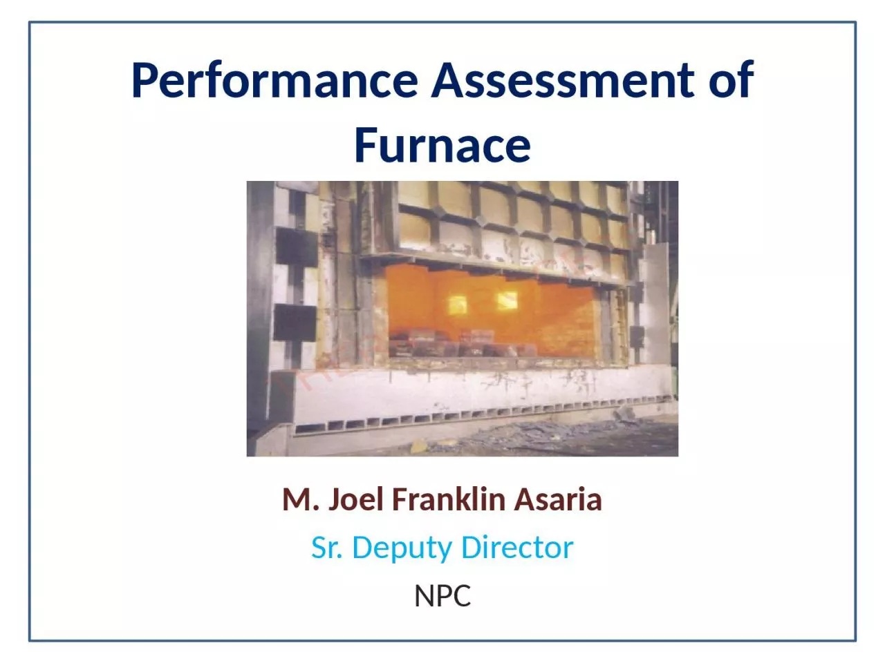
1. Performance Assessment of FurnaceM. Joel Franklin AsariaSr. Deputy DirectorNPC
2. Operation Of Furnace
3. Pusher Type Furnaces
4. Forging FurnacesUsed for preheating billets and ingots to attain a ‘forge’ temperature. The furnace temperature is maintained at 1200 to 1250oC.Forging furnaces, use an open fireplace system and most of the heat is transmitted by radiation. The typical loading in a forging furnace is 5 to 6 tones with the furnace operating for 16 to 18 hours daily. The total operating cycle can be divided into (i) heat-up time (ii) soaking time and (iii) forging time. Specific fuel consumption depends upon the type of material and number of ‘reheats’ required.
5. Forging Furnace
6. Heat Transfer in FurnacesRadiation from the flame, hot combustion products and the furnace walls and roofConvection due to the movement of hot gases over the stock surface.
7. Performance Terms and DefinitionsFurnace Efficiency, η = = 2. Specific Energy Consumption =
8. Measurement ParametersWeight of stock / Number of billets heatedTemperature of the stocks/billets Temperature of furnace walls, roof etcArea of furnace walls, roof etcFlue gas temperatureFlue gas analysisFuel oil consumption
9. Furnace EfficiencyThe efficiency of a furnace is the ratio of useful heat output to heat input. The direct determination of furnace efficiency is carried out as follows.The quantity of heat to be imparted (Q) to the stock can be found from the formula Where Q = Quantity of heat in kCal m = Weight of the material in kg Cp = Mean specific heat, kCal/kg oC t2 = Final temperature desired, oC t1 = Initial temperature of the charge before it enters the furnace, oC
10. Thermal Efficiencies For Common Industrial FurnacesFurnace TypeTypical thermal efficiencies (%)1) Low Temperature furnacesa. 540 – 980 oC (Batch type)20-30b. 540 – 980 oC (Continous type)15-25c. Coil Anneal () radiant type5-7d. Strip Anneal Muffle7-122) High temperature furnacesa. Pusher, Rotary7-15b. Batch forge5-103) Continuous Kilna. Hoffman25-90b. Tunnel20-804) Ovensa. Indirect fired ovens (20oC-370oC)35-40b. Direct fired ovens (20oC-370oC)35-40
11. Performance Evaluation of a Typical Furnace Heat losses in industrial heating Furnaces
12. What are the furnace losses ?Wall losses:Radiation loss Air infiltration from furnace opening.Stack loss (Waste-gas loss)Air infiltration Material handling loss Cooling media losses Radiation (opening) loss Stored Heat Loss:Wall Loss:
13. Furnace Efficiency CalculationExample: An oil-fired reheating furnace has an operating temperature of around 1340oC. Average fuel consumption is 400 litres/hour. The flue gas exit temperature after air preheater is 750oC. Air is preheated from ambient temperature of 40 oC to 190 oC through an air pre-heater. The furnace has 460 mm thick wall (x) on the billet extraction outlet side, which is 1 m hight (D) and 1 m wide. The other data are as given below. Calculate the efficiency of the furnace by both indirect and direct method.
14. Trial DataFlue gas temperature after air preheater = 750oCAmbient temperature = 40oCPreheated air temperature = 190oCSpecific gravity of oil = 0.92Average fuel oil consumption = 400 Litres / hr = 400 x 0.92 =368 kg/hrCalorific value of oil = 10000 kCal/kgAverage O2 percentage in flue gas =12%Weight of stock = 6000 kg/hrSpecific heat of Billet = 0.12 kCal/kg/0CSurface temperature of roof and side walls = 122 oCSurface temperature other than heating and soaking zone = 85 oC
15. Furnace Efficiency (Direct Method)
16. Furnace Efficiency (Indirect Method)
17. 2. Loss Due to Evaporation of Moisture Present in Fuel % Loss Where, M - % Moisture of in 1 kg of fuel oil (0.15 kg/kg of fuel oil)Tfg - Flue Gas TemperatureTamb - Ambient temperatureGCV - Gross Calorific Value of Fuel 0.15 {584 + 0.45 (750-40)} % Loss = ------------------------------ x 100 = 1.36 % 10000 Where, H2 – % of H2 in 1 kg of fuel oil (0.1123 kg/kg of fuel oil) = 9 x 0.1123 {584 + 0.45 (750-40)} ------------------------------------- x 100 = 9.13 % 10000
18. 4. Heat Loss due to Openings:The shape of the opening is square and D/X = 1/0.46 = 2.17The factor of radiation (Refer Figure 2.4) = 0.71Black body radiation corresponding to 1340oC = 36.00 kCal/cm2/hr(Refer Figure 2.5 On black body radiation) = 100 cm x 100 cm Area of opening = 10000 cm2Emissivity = 0.8 Total heat loss = Black body radiation x area of opening x factor of radiation x emissivity =36 x 10000 x 0.71 x 0.8 = 204480 kCal/hrEquivalent Oil loss = 204480/10,000 = 20.45 kg/hr% of heat loss = 20.45 /368 x 100 = 5.56 % Heat loss due to openings can be calculated by computing black body radiation at furnace temperature, and multiplying these values with emissivity and the factor of radiation through openings.Use fig. for black body radiation loss and Factor of radiation through openings
19. Figure 2.4 Factor for Determining the Equivalent of Heat Release from Openings to the Quality of Heat Release from Perfect Black Body
20. Figure 2.5 Graph for Determining Black Body Radiation at a Particular Temperature
21. 5. Heat Loss through Skin:5a). Heat loss through roof and sidewalls: Total average surface temperature = 122oC Heat loss at 122 oC = 1252 kCal / m2 / hr Total area of heating + soaking zone = 70.18 m2 Heat loss = 1252 kCal / m2 / hr x 70.18 m2 = 87865 kCal/hr Equivalent oil loss (a) = 8.78 kg / hr 5b). Total average surface temperature of area other than heating and soaking zone= 85oC Heat loss at 85oC = 740 kCal / m2 / hr Total area = 12.6 m2 Heat loss = 740 kCal / m2 / hr x 12.6 m2 = 9324 kCal/hr Equivalent oil loss (b) = 0.93 kg / hr Total loss of fuel oil = a + b = 9.71 kg/hr Total percentage loss = 9.71 / 368 = 2.64%
22. Quantity of Heat Release at Various Temperatures
23. Furnace Efficiency (Indirect Method) 1. Sensible heat loss in flue gas = 57.29%2. Loss due to evaporation of moisture in fuel = 1.36 % 3. Loss due to evaporation of water formed from H2 in fuel = 9.13 %4. Heat loss due to openings = 5.56 %5. Heat loss through skin = 2.64% Total losses = 75.98 % Furnace Efficiency = 100 – 75.98 = 24.02 %Specific Energy Consumption = 400 litre /hour (fuel consumption) 6Tonnes/hour (Wt of stock) = 66.6 Litre of fuel /tonne of Material (stock)
24. General Fuel Economy Measures in Furnaces1) Complete combustion with minimum excess air2) Correct heat distribution3) Operating at the desired temperature 4) Reducing heat losses from furnace openings5) Maintaining correct amount of furnace draught6) Optimum capacity utilization7) Waste heat recovery from the flue gases8) Minimum refractory losses9) Use of Ceramic Coatings
25. 1) Complete Combustion with Minimum Excess Air The amount of heat lost in the flue gases depends upon amount of excess air. In the case of a furnace carrying away flue gases at 900oC, % heat lost is shown in table : Table Heat Loss in Flue Gas Based on Excess Air LevelExcess Air% of total heat in the fuel carried away by waste gases (flue gas temp. 900oC)25485055756310071
26. 2) Correct Heat DistributionHeat distribution in furnace Alignment of burners in furnace Prevent flame impingement. To avoid high flame temperature, damage of refractory and for better atomizationAlign burner properly to avoid touching the materialto reduce scale loss
27. 3) Operating at Desired TemperatureSlab Reheating furnaces 1200oCRolling Mill furnaces 1200oCBar furnace for Sheet Mill 800oCBogey type annealing furnaces- 650oC -750oC CORRECT TEMPERATURE ENSURES GOOD QUALITY PRODUCTS.TEMPERATURE HIGHER THAN REQUIRED WOULD ONLY USE UP MORE FUELTemperature for Different FurnacesFor maintaining temperature, do not leave it to operator judgment, Use ON/OFF controls
28. 4) Reducing Heat Loss from Furnace OpeningsThe heat loss from an opening can be calculated using the formula: Q=4.88 x T 4 x a x A x H … k.Cal/hr 100T: absolute temperature (K), a: factor for total radiationA: area of opening, H: time (Hr) Heat loss through openings consists of direct radiation and combustion gas that leaks through openings. Keeping the doors unnecessarily open leads to wastage of fuelInspection doors should not kept open during operationBroken and damaged doors should be repaired
29. 5) Maintaining correct amount of furnace draughtNegative pressures : air infiltration- affecting air-fuel ratio control, problems of cold metal and non-uniform metal temperatures, Positive Pressure: Ex-filtration -Problems of leaping out of flames, overheating of refractories, burning out of ducts etc.
30. 6) Optimum capacity utilizationThere is a particular loading at which the furnace will operate at maximum thermal efficiency. Best method of loading is generally obtained by trial-noting the weight of material put in at each charge, the time it takes to reach temperature and the amount of fuel used. Mismatching of furnace dimension with respect to charge and production schedule. Coordination between the furnace operator, production and planning personnel is needed.
31. 7) Waste heat recovery from the flue gases Stock preheating Combustion air preheating Using waste heat for other process
32. 8. Minimizing Wall Losses About 30% of the fuel input to the furnace generally goes to make up for heat losses in intermittent or continuous furnaces. The appropriate choice of refractory and insulation materials is needed for high fuel savings in industrial furnaces. The extent of wall losses depend on: Emissivity of wallThermal conductivity of refractoriesWall thicknessWhether furnace is operated continuously or intermittently
33. Radiation Heat Loss from Surface of FurnaceThe quantity (Q) of heat release from a reheating furnace is calculated with the following formula: wherea : factor regarding direction of the surface of natural convection ceiling = 2.8, side walls = 2.2, hearth = 1.5tl : temperature of external wall surface of the furnace (°C)t2 : temperature of air around the furnace (°C)E: emissivity of external wall surface of the furnace
34. 9.Use of Ceramic Coatings The benefits of applying a high-emissivity ceramic coating:-Rapid heat-upIncreased heat transfer at steady stateImproved temperature uniformityIncreased refractory lifeElimination of refractory dust.
35. Furnace InstrumentationSl.No.Parametersto be measuredLocation ofMeasurementInstrumentRequiredRequiredValue1.Furnace soaking zone temperature (reheating furnaces)Soaking zone side wallPt/Pt-Rh thermocouple with indicator and recorder1200-1300oC2.Flue gasFlue gas exit from furnace and entry to re-cuperatorChromel Alummel Thermocouple with indicator700oCmax.3.Flue gasAfter recuperatorHg in steel thermometer300oC (max)4.Furnace hearth pressure in the heating zone Near charging end side wall over hearth levelLow pressure ring gauge+0.1 mm. of Wg5.Flue gas analyserNear chargingend side wall end sideFuel efficiency monitor for oxygen & temperature. O2% = 5t = 700oC(max)6.Billet temperaturePortableInfrared Pyrometer or optical pyrometer----
36. Thank you