
Operating Instructions Parts Manual Please read and retain these instructions for future reference Kindly read this manual carefully before making any effort to assemble install operate or mainta ID: 846815
Download Pdf The PPT/PDF document "LCP4 and LCP5" is the property of its rightful owner. Permission is granted to download and print the materials on this web site for personal, non-commercial use only, and to display it on your personal computer provided you do not modify the materials and that you retain all copyright notices contained in the materials. By downloading content from our website, you accept the terms of this agreement.

1 LCP4 and LCP5 Operating Instructions & P
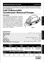
LCP4 and LCP5 Operating Instructions & Parts Manual Please read and retain these instructions for future reference. Kindly read this manual carefully before making any effort to assemble, install, operate or maintain our pumps. Please protect yourself and others by observing all safety information. A failure to comply with instructions could result in personal injury and / or property damage! Lubi Submersible Condensate Removal Pumps Description Lubi designed and manufactured condensate pump automatically removes water dripping off an air conditioner evaporative coil. This epoxy encapsulated submersible pump is designed for a variety of applications where reliable, automatic pump operation is required. This unit operates efficiently on an 115V, 60 Hz, single phase motor that includes 6 feet long, 3 prong power cord and a check valve. Additionally, the motor is protected from overheating and damage. If automatically shuts off with sudden rise in temperature and restarts after cooling down. Specifications Figure 1 Discharge size.................................................................Power supply..................................................................................................Volts....................................................................................................................Hz........................................................................................................................Cord size ................................................................Temperature...............................................................................Tank capacity..................................
2 ........................................
....................................................Wetted Materials of Construction................. 3/8 O.D. Plastic barb fitting1 Phase115V60HzSJTW 3C x 18 AWG, 6 feet - lengthLCP4 and LCP5 - 86°FLCP5 - 1.0 quartRynite, ABS, PP, SS, Buna-N and Silicon Model MotorFull LoadAmps RPM LCP4LCP5 Motor Cover Tank Impeller Shaft 1.01.0 3000 RyniteRynite Stainless SteelStainless Steel NAABS PolypropylenePolypropylene Performance (without check valve) Model LCP4LCP5 GPH of Water @ Total Feet of Head 1 3 5 10 100100 89 68 95 Shut OffHead (Ft) 1111 Switch Setting 2.02.0 On Off 1.01.0 2 Dimensions Figure 7 LCP4 and LCP5 Operating Instructions & Parts Manual Lubi Submersible Condensate Removal Pumps 2.8 (71.98) 1.2 (30.55) 1.8 (47) 3.1 (79) 2.6 (67.05) 5.5 (142) 8.4 (214.03) 4.1 (104.2) 3.6 (91.7) 1.48 (37.45) 0.1 (3.7) 10.23 (260) 2.9 (75) 4.5 (114) 8.6 (220) 9.8 (250.67) 0.4 (10) 3.9 (99) 4.9 (126.31) 4.6 (117.7) 3.5 (89) Figure 6 LCP4 LCP5 3 Model LCP4 is the pump only.Model LCP5 is supplied with a sump pan, 20 ft. of tubing, & safety control switch. Before installing the pump, inspect it carefully and make sure that there are no damaged parts. If damage has occurred, contact and file a claim immediately with the carrier that delivered the pump. Unpacking and InspectionGeneral Safety InformationTo reduce the risk of electric shock, unplug the unit before servicing. The pump is equipped with a grounding conductor and grounding-type attachment plug. Make sure it is connected only to a properly grounded grounding-type receptacle. If a 2-prong wall receptacle is present, it must be replaced
3 with a properly grounded 3-prong recepta
with a properly grounded 3-prong receptacle installed in accordancewith codes and ordinances that apply.NOTE: This equipment is for use on 115 volt (single phase) only and is supplied with an approved 3-prong plug and grounding cord. Follow all required electrical and safety codes when wiring an electrically driven pump. Ensure the power source is compatible with the requirements of your equipment. A qualified electrician should do all wiring. Avoid kinking the power cord. If any cords are worn, repair or replace them immediately. Protect the power cord from sharp objects, chemicals, hot surfaces, and oil. PERSONAL SAFETY CONCERNS Always wear safety glasses when working on pumps. Make work area and shop child safeutilize master switches and locks, and remove all keys. Keep work area well-lighted. Keep others at a safe distance away while working. Keep work area clean and tidy, and put all unused tools and equipment away. Never touch or handle the pump, while plugged in, with wet hands or when standing in water or on a damp surfaceInstallationBe sure the pump isalways electricallygrounded to an acceptable electricalground such as a ground wire system,a grounded water pipe, or a properlygrounded metallic raceway. Do not cut off the round grounding pin. 1. 1. 1. 1. 1. 1. 1. The 3/8" check valve should be attached to the 1/4" N.P.T. elbow. Make sure not to over-tighten. The pump should be put in a sump tank or other appropriate container. Make sure that the drip pan is at least 3 deep. Run the discharge line (3/8 vinyl tubing) up to the minimum distance req
4 uired. Make sure that the discharge line
uired. Make sure that the discharge line is not more than 10 ft. It is advisable to slant the horizontal run down slightly to gain the benefit of gravity. (Figure 4)2. Power should be switched off before making any connections. All wiring must comply with local and national codes.3. Line voltage: Connect power cord to line voltage as per motor specification.Power cord must be connected to an uninterrupted source of power. WATER LEVEL DOWN Figure 2 COM NO NC Connect here to turn thermostat off. Connect here to turn alarm on. Operating Instructions & Parts Manual Models LCP4 and LCP5 4 1/4 SCREW 1/4 NUT SWITCHASSEMBLY Figure 3 Installation (Continued)4. Safety switch: (Figure 3,5) Use a class 2 low voltage circuit to connect the safety switch. Thermostat circuit can be controlled by connecting COM and NO in series with low voltage thermostatic circuit to shut the AC/Thermostat circuit. Alternatively, the heating/cooling COM and NC switch contacts can be used to trigger a low voltage alarm circuit (connected in series) if the heating/cooling system cannot be troubled. The safety switch comes with leads connected to 1. 1. Figure 4 NOT MORETHAN 10 FEET 3 MINIMUM SLOPE DOWNWARD 1. 1. 1. 1. 1. the COM and NO switch terminals. Refer to Figure 2 to connect the "NC" circuit.Never remove the A small Breather Tube (Figure 8) is enclosed inside the power cord. Make sure that the breather tube is not blocked to ensure proper functionality of the pressure switch. 1. Follow all the instruction in the Installation section. 2. Place the pump (LCP4 only) in a 3 drip pan. 3. Provide power to the pump. 4. Fill the drip pan with water until the pump starts to
5 operate. The pump should start to operat
operate. The pump should start to operate as the water level reaches 2.Before attempting to repair or remove any component from this Lubi condensate pump, ensure that all power sources are disconnectedscrews that hold the diaphragm cover in place. Trying to remove parts in the switch could cause an electric shock.A properly grounded receptacle must be installed to reduce the risk of electrical shock. Always disconnect pump from its power source before handling.Pre-operation Testing of PumpDo not pump materials (Flammable, caustic, etc.) unless the pump is specifically designed and designated to handle them.Maintenance LCP4 and LCP5 Operating Instructions & Parts Manual Lubi Submersible Condensate Removal Pumps 5 Maintenance (Continued)If the condensate pump fails to operate, please check the following:1. Before attempting to repair or remove any component from this Lubi condensate pump, ensure that all power sources are disconnected.2. Make sure that the pump is getting power supply. Check the circuit breaker or try another power outlet to be sure. 3. Make sure that the intake screen is free of any sand or dirt. 4. Inlet and outlet piping should be checked. Clean as necessary. Be sure there are no foreign objects in the line that would inhibit flow. 5. Make sure that the impeller is not broken or jammed. 1. 1. 1. 1. 1. 1. 1. 6. Minerals deposit around
6 the impeller should be scraped off. Fir
the impeller should be scraped off. First, gently remove the impeller from the shaft and remove the mineral deposits. Then apply a few drops of oil where impeller shaft enters the motor. Press the impeller on to the shaft and make sure there is 1/16 gap between Impeller and impeller back plate. 7water.8. Periodically, inlet and outlet piping should be checked. Clean as necessary. Be sure there are no foreign objects or kinks in the line that would inhibit flow.The four screws that hold the diaphragm cover in place should never be removed. There are no repairable parts in the switch mechanism and removing or loosening the diaphragm cover could cause an electrical shock hazard.1. 1. 1. 1. . Tank should be cleaned with lukewarm Figure 5 Operating Instructions & Parts Manual Models LCP4 and LCP5 6 Troubleshooting Chart Symptom Possible Cause(s) Corrective Action 1. If fuse is blown, replace with appropriate size2. If the voltage is less than the minimum required, inspect the wiring size at the main switch on the property. If the size is OK, contact the local electric company or hydroelectric authority 3. Replace the pump4. If the impeller wont turn, locate the source of the clog and remove1. Install or replace the check valve1. Replace the pump2. Remove the pump and clean it and the piping1. If the voltage is less than the minimum required, inspect the wiring size at the main switch on the property. If the size is OK, contact the local electric company or hydroelectric authority2. Flush out the impeller or, if cannot be cleaned,Replace the pump.3. Replace the pump4. Remove the pump and cl
7 ean the piping2. 2. 2. 2. 2. 2. 2. 2. 2.
ean the piping2. 2. 2. 2. 2. 2. 2. 2. 2. 2. 2. 2. 2. 1. Bad fuse2. Low voltage3. Defect inside motor4. Clogged impeller1. Water back flowing from piping1. Faulty float switch2. Restricted discharge (blockage in piping)1. Low voltage2. Clogged impeller3. Worn impeller or defective parts4. Restricted discharge (blockage in piping)2. 4. Pump wont startPump cycles too oftenPump wont shut offPump starts but pumps little or no water Hazardous voltage; risk ofelectric shock, personalinjury, or death. Unplug the pump beforeattempting to clean or service the unit. LCP4 and LCP5 Operating Instructions & Parts Manual Lubi Submersible Condensate Removal Pumps 7 1210 Figure 8 - Repair Parts Illustration Repair Parts List Ref.No. Description Part Number for Models: LCP4 LCP5 Quantity 11 Bottom CoverCheck ValveImpelleroluteImpeller Back Plate1/4 NPT Elbow / 125-250 VACTank PP01014GPP01019G PP01014GPP01019G Monday thru Friday - 8:00 am to 4:30 pm E.S.T. For Repair Parts, call 570-585-2195 Operating Instructions & Parts Manual LCP4 and LCP5 12 11 6 2 4 3 9 8 7 5 1 Breather tube 10 LIMITED WARRANTYLUBI WARRANTS TO THE ORIGINAL CONSUMER PURCHASER (PURCHASER) OF ITS PRODUCTS THAT THEY ARE FREE FROM DEFECTS IN MATERIAL & WORKMANSHIP. IF WITHIN TWO (2) YEARS FROM THE DATE OF ORIGINAL CONSUMER PURCHASE ANY SUBMERSIBLE CONDENSATE REMOVAL PUMPS, SHALL PROVE TO BE DEFECTIVE, IT SHALL BE REPAIRED OR REPLACED AT LUBIS OPTION, SUBJECT TO TERMS & CONDITION SET FORTH BELOW.GENERAL TERMS & CONDITIONS : PURCHASER MUST PAY ALL LABOR AND SHIPPING CHARGES NECESSARY TO REPLACE PRODUCT COVERED BY THE WARRANTY. THE
8 WARRANTY SHALL NOT APPLY TO ACTS OF GOD
WARRANTY SHALL NOT APPLY TO ACTS OF GOD, NOR SHALL IT APPLY TO PRODUCTS, WHICH IN SOLE JUDGEMENT OF LUBI, HAVE BEEN SUBJECTED TO NEGLIGENCE, ABUSE, ACCIDENT, MISAPPLICATION, TAMPERING, ALTERATION; NOR DUE TO DEFECTS OR MALFUNCTIONS, RESULTING FROM THE FAILURE TO INSTALL, OPERATE, OR MAINTAIN THE UNIT IN ACCORDANCE WITH PRINTED INSTRUCTION PROVIDED ; NOR TO UNITS WHICH IS MOVED FROM ITS ORIGINAL INSTALLATION LOCATION ; NOR IF THE UNIT IS USED FOR THE PURPOSES OTHER THAN FOR WHAT IT WAS DESIGNED AND MANUFACTURED ; NOR TO UNITS WHICH ARE NOT INSTALLED IN ACCORDANCE WITH APPLICABLE LOCAL CODES, ORDINANCES, AND ORIGINAL TRADE PRACTICES.LABOR & COSTS : LUBI SHALL POSSESS SOLE RIGHT TO DETERMINE WHETHER TO REPAIR OR REPLACE DEFECTIVE PRODUCT, PARTS OR COMPONENTS. LUBI SHALL IN NO EVENT BE LIABLE FOR THE COST OF FIELD LABOR OR OTHER CHARGES INCURRED BY ANY CUSTOMER IN REMOVING AND/OR REAFFIXING ANY LUBI PRODUCT, PART OR COMPONENT.PRODUCT IMPROVEMENT : LUBI RESERVES THE RIGHT TO CHANGE OR IMPROVE ITS PRODUCTS OR OTHER COMPONENT WITHOUT OBLIGATION TO PROVIDE SUCH A CHANGE OR IMPROVEMENT FOR THE UNITS PREVIOUSLY SOLD AND/OR SHIPPED. WARRANTY EXCLUSIONS : LUBI SPECIFICALLY DISCLAIMS THE IMPLIED WARRANTIES OF MERCHANTABILITY AND FITNESS FOR A PARTICULAR PURPOSE AFTER TERMINATION OF THE WARRANTY PERIOD SET FORTH HEREIN. SOME STATES DO NOT PERMIT SOME OR ALL OF THE ABOVE WARRANTY LIMITATIONS AND THEREFORE, SUCH LIMITATIONS MAY NOT APPLY TO YOU. NO WARRANTIES OR REPRESENTATIONS AT ANY TIME MADE BY ANY REPRESENTATIVES OF LUBI SHALL VARY OR EXPAND THE PROVISION HEREOF. LCP4 and LCP5 Operating Instructions & Parts Manual Lubi Submersible Condensate Removal Pumps