

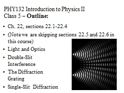
Introduction to Physics II Class 6 Outline Ch 23 sections 236238 The Thin Lens Equation The LensMakers Equation Image Formation with Spherical Mirrors Slide from http hyperphysicsphyastrgsueduhbasevisioncolconhtml ID: 248478
Download Presentation The PPT/PDF document "PHY132" is the property of its rightful owner. Permission is granted to download and print the materials on this web site for personal, non-commercial use only, and to display it on your personal computer provided you do not modify the materials and that you retain all copyright notices contained in the materials. By downloading content from our website, you accept the terms of this agreement.


Slide1
PHY132
Introduction to Physics II Class 6 – Outline:
Ch. 23, sections
23.6-23.8
The Thin Lens Equation
The
Lens-Maker's Equation
Image
Formation with Spherical MirrorsSlide2
Slide from http
://hyperphysics.phy-astr.gsu.edu/hbase/vision/colcon.htmlResponse Curves for the three types of cones in the retina of the human eye.Slide3
Additive Primary Colours (light bulbs)and Subtractive Primary Colours (ink)Slide4
Why the Sky Is Blue
For small scattering particles, like nitrogen or oxygen molecules, higher frequency blue light is scattered much more readily than lower frequency red light.Slide5
Why the Sky Is Blue
Slide6
If molecules in the sky scattered orange light instead of blue light, the sky would beA. orange.
yellow. green.blue.
Why Sunsets Are Red
CHECK YOUR
NEIGHBOUR
Slide7
Why Sunsets Are Red
Light that is least scattered is light of low frequencies, which best travel straight through air.Slide8
If molecules in the sky scattered orange light instead of blue light, sunsets would beA. orange.
yellow. green.blue.
Why Sunsets Are Red
CHECK YOUR
NEIGHBOUR
Slide9
Image formation at a spherical interface
R is positive means surface is convex toward the objectR is negative means surface is concave toward objects
o
is positive means object is to the left of interface
s
i
is positive means image is real, to the right of interface
s
o
s
iSlide10
Lensmaker’s Formula
s
o
2
s
i
2
s
o
1
s
i
1Slide11
Converging Lens
Focal Point
Focal length,
f
NOTE: Focal length is defined for initially
parallel
rays.Slide12
Diverging Lens
Virtual Focal Point
Negative Focal length,
−
f
Rays appear to emerge from Virtual Focal PointSlide13
You can use the sun’s rays and a lens to start a fire. To do so, you should use
QuickCheck 23.8
A converging lens.
A diverging lens.
Either a converging or a diverging lens will work if you use it correctly.
Slide14
Focusing Power
Traditionally, lenses are specified not by their focal length, but by the inverse of their focal length.This is called “focusing power”
The S.I. unit of focusing power is
m
–1
Traditionally, this unit is called the “diopter,” abbreviated D.
Slide15
Diverging rays through a Converging Lens
Focal length,
f
If an object emits rays at the focal point, they end up being parallel on the other side of the converging lens.Slide16
What will happen to the rays emerging to the right of the lens if the face is moved a little closer to the lens?They will remain parallel.They will diverge (spread out).
They will converge (toward a focus).
fSlide17
What will happen to the rays emerging to the right of the lens if the face is moved a little further away from the lens?They will remain parallel.They will diverge (spread out).
They will converge (toward a focus).
fSlide18
Diverging rays through a Converging Lens
Focal length,
f
s
s’
Thin Lens Equation:Slide19
Thin Lens Equation: sign conventionss
s’
f
object
image
s
is positive for objects to the left of lens, negative for objects to the right of lens (virtual objects).
s’
is positive for images to the right of lens, negative for images to the left of lens (virtual images).
f
is positive for converging lenses, negative for diverging lenses.Slide20
ExampleA lens has a focal power of +10 D.A 1 cm high object is placed 15 cm in front of the lens.Where does the image form?
+10D
s
= 15 cm
1 cmSlide21
A lens produces a sharply focused, inverted image on a screen. What will you see on the screen if the lens is removed?
An inverted but blurry image.
An image that is dimmer but otherwise unchanged.
A sharp, upright image.
A blurry, upright image.
No image at all.
QuickCheck 23.9
Slide 23-96Slide22
A lens produces a sharply focused, inverted image on a screen. What will you see on the screen if a piece of dark paper is lowered to cover the top half of the lens?
An inverted but blurry image.
An image that is dimmer but otherwise unchanged.
Only the top half of the image.
Only the bottom half of the image.
No image at all.
QuickCheck 23.10
Slide 23-98Slide23
A lens produces a sharply focused, inverted image on a screen. What will you see on the screen if the lens is covered by a dark mask having only a small hole in the center?
An inverted but blurry image.
An image that is dimmer but otherwise unchanged.
Only the middle piece of the image.
A circular diffraction pattern.
No image at all.
QuickCheck 23.11
Slide 23-100Slide24
MagnificationThe absolute magnitude of the magnification |M
| is defined to be the ratio of image height to object height.A positive value of M indicates that the image is upright relative to the object. A negative value of M indicates the image is inverted relative to the object.
Note that when
s
and
s
’ are both positive,
M
is negative.Slide25
ExampleA lens has a focal power of +10 D.A 1 cm high object is placed 15 cm in front of the lens.How large is the image, and is it upright or inverted?
+10D
s
= 15 cm
1 cmSlide26
Ray Tracing
With a converging thin lensSlide27
Ray TracingWith a diverging thin lensSlide28
Slide 23-119
QuickCheck 23.14
Light rays are converging to point 1. The lens is inserted into the rays with its focal point at point 1. Which picture shows the rays leaving the lens?Slide29
The figure shows a
concave mirror
, a mirror in which the edges curve
toward
the light source.
Rays parallel to the optical axis reflect and pass through the focal point of the mirror.
Image Formation with Concave Spherical Mirrors
Slide 23-139Slide30
This focus only exists for rays that are
close
to the axis.Slide31
This focus only exists for rays that are
close
to the axis.
No good focus
This is called “spherical
abberation
”Slide32
A Real Image Formed by a Concave Mirror
Slide 23-140Slide33
The figure shows parallel light rays approaching a mirror in which the edges curve
away from
the light source.
This is called a
convex mirror.
The reflected rays appear to come from a point behind the mirror.
Image Formation with Convex Spherical Mirrors
Slide 23-141Slide34
A Real Image Formed by a Convex Mirror
Slide 23-142Slide35
For a spherical mirror with negligible thickness, the object and image distances are related by:
where the focal length
f
is related to the mirror’s radius of curvature by:
The Mirror Equation
Slide 23-146Slide36
You see an upright, magnified image of your face when you look into magnifying “cosmetic mirror.” The image is located
Clicker Question
Slide 23-147
In front of the mirror’s surface.
On the mirror’s surface.
Behind the mirror’s surface.
Only in your mind because it’s a virtual image.
Slide37
Before Class 7 on MondayComplete Problem Set 2 on
MasteringPhysics due Sunday at 11:59pm on Ch. 23. Please read Knight Pgs. 694-711: Ch.24Please do the short pre-class
quiz on
MasteringPhysics
by Sunday night.
Something to think about: When you look at an object with a telescope, it looks bigger. What, exactly, about the object is bigger? What are the units of image size?