
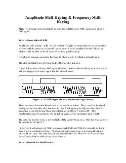
Intro to Generation of ASK Am plitude shift keying ASK in the contex t of digital com unications is a m odulation process which im parts to a sinusoid two or re discre te am plitud leve ls These ar related to the num ber of levels adopted by the d ID: 13031
Download Pdf The PPT/PDF document "Amplitude Shift Keying Frequency Shift ..." is the property of its rightful owner. Permission is granted to download and print the materials on this web site for personal, non-commercial use only, and to display it on your personal computer provided you do not modify the materials and that you retain all copyright notices contained in the materials. By downloading content from our website, you accept the terms of this agreement.


Amplitude Shift Keying & Frequency Shift Keying Aim: To generate and demodulate an amplitude shift keyed (ASK) signal and a binary FSK signal. Intro to Generation of ASK For a binary message sequence there are two levels, one of which is typically zero. Thus the modulated waveform consists of bursts of a sinusoid. There are sharp discontinuities shown at the transition points. These result in the signal having an unnecessarily wide bandwidth. Bandlimiting is generally introduced before transmission, in which case these discontinuities would be One of the disadvantages of ASK, compared with FSK and PSK, for example, is that it has not got a constant envel sequence; instead, their outputs would be a bandlimited version. Thus further processing - by some sort of decision-making circuitry for example - would be necessary. Thus demodulation is a two-stage process: 1. recovery of the bandlimited bit stream 2. regeneration of the binary bit stream Figure 4 illustrates. Figure 4: the two stages of the demodulation process Modeling an ASK Generator It is possible to model the rather basic generator shown in Figure 2. The switch can be modeled by one half of a DUAL ANALOG SWITCH module. Being an analog switch, the carrier frequency would need to be in the audio range. The TTL output from the SEQUENCE GENERATOR is connected directly to the CONTROL input of the DUAL ANALOG SWITCH. For a synchronous carrier and message use the 8.333 kHz TTL sample clock (filtered by a TUNEABLE LPF) and the 2.083 kHz sinusoidal message from the MASTER SIGNALS module. If you need the TUNEABLE LPF for bandlimiting of the ASK, use the sinusoidal output from an AUDIO OSCILLATOR as the carrier. For a synchronized message as above, tune the oscillator close to 8.333 kHz, and lock it there with the sample clock connected to its SYNCH input. This arrangement is shown modeled in Figure 5. Introduction to Part II: FSK Generation: As its name suggests, a frequency shift keyed transmitter has its frequency shifted by the message. Although there could be more than two frequencies involved in an FSK signal, in this experiment the message will be a binary bit stream, and so only two frequencies will be involved. The word ‘keyed’ suggests that the message is of the ‘on-off’ (mark-space) variety, such as one (historically) generated by a morse key, or more likely in the present context, a binary sequence. The output from such a generator is illustrated in Figure 1 below. Conceptually, and in fact, the transmitter could consist of two oscillators (on frequencies f1 and f2), with only one being connected to the output at any one time. This is shown in block diagram form in Figure 2 below. The output from each BPF looks like an amplitude shift keyed (ASK) signal. These can be demodulated asynchronously, using the envelope. The decision circuit, to which the outputs of the envelope detectors are presented, selects the output which is the most likely one of the two inputs. It also re-shapes the waveform from a bandlimited to a rectangular form. This is, in effect, a two channel receiver. The bandwidth of each is dependent on the message bit rate. There will be a minimum frequency separation required of the two tones. Hint: You are advised to read ahead, before attempting the experiment, to consider the modelling of this demodulator. Unlike most TIMS models, you are not free to choose parameters - particularly frequencies. If they are to be tuned to different frequencies, then one of these frequencies must be 2.083 kHz (defined as the MARK frequency). This is a restriction imposed by the BIT CLOCK REGEN module, of which the BPF are sub-systems. As a result of this, most other frequencies involved are predetermined. Make sure you appreciate why this is so, then decide upon: bit clock rate SPACE frequency envelope detector LPF characteristics Synchronous Demodulator: In the block diagram of Figure 4 two local carriers, on each of the two frequencies of the binary FSK signal, are used in two synchronous demodulators. A decision circuit examines the two outputs, and decides which is the most likely. Experimental Procedure: Generation: Scheme # 1: A VCO module is ideally suited for the generation of a continuous phase FSK signal, as shown in Figure 6. In FSK mode the VCO is keyed by the message TTL sequence. Internal circuitry results in a TTL HI switching the VCO to frequency f1, while a TTL LO switches it to frequency f2. These two frequencies may be in the audio range (front panel toggle switch LO), or in the 100 kHz range (front panel toggle switch HI). The frequencies f1 and f2 are set by the on-board variable resistors RV8 and RV7 respectively, while a continuous TTL HI or a TTL LO is connected to the DATA input socket. In FSK mode neither of the front panel rotary controls of the VCO is in operation. Scheme # 2: Figure 7 shows a model of the arrangement of Figure 2. It switches either one of two tones to the output, in response to the message sequence. If you do not have extra UTILITIES and TUNEABLE LPF modules, then complete just one arm of the demodulator. Alignment requires the BPFs to be tuned to the MARK and SPACE frequencies. The first is already done (2.083 kHz is already pre-set with SW1); the other is set with the VCO (already pre-set with SW2). Note that the specified bit rate is, by TIMS standards, rather low. The average oscilloscope display can be a little flickery. Use a short sequence, and the SYNC signal from the SEQUENCE GENERATOR to ext. trig. Phase Locked Loop: A phase locked loop is shown in block diagram form in Figure 5, and modelled in Figure 9.