
Split or dualsupply op amp circuit design is straightforward because op amp inputs and outputs are referenced to the normally grounded center tap of the supplies In the majority of splitsupply applications sig nal sources driving the op amp inputs a ID: 35488
Download Pdf The PPT/PDF document "Analog Applications Journal Analog and M..." is the property of its rightful owner. Permission is granted to download and print the materials on this web site for personal, non-commercial use only, and to display it on your personal computer provided you do not modify the materials and that you retain all copyright notices contained in the materials. By downloading content from our website, you accept the terms of this agreement.

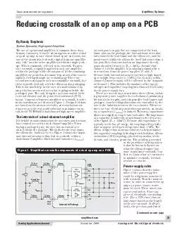
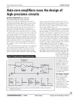
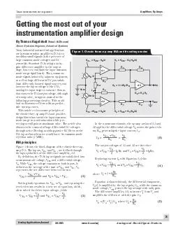
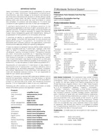
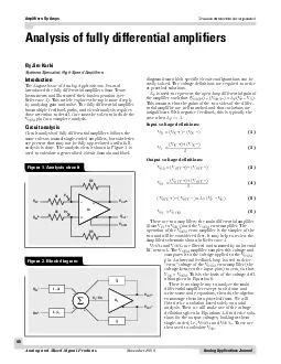


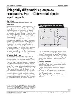

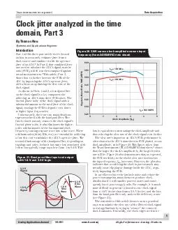
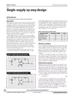
20Analog Applications Journal Analog and Mixed-Signal ProductsNovember 1999Texas Instruments IncorporatedAmplifiers: Op AmpsSingle-supply op amp designIntroductionMost portable systems have one battery, thus the popularityof portable equipment results in increased single-supplyapplications. Split- or dual-supply op amp circuit design is-nal sources driving the op amp inputs are referenced toWhen signal sources are referenced to ground, single- Input currentIIN0 Input offset-voltageVOS0 Input impedanceZIN¥ Output impedanceZOUT0 Gaina¥ Table 1. Ideal op amp parameter values + V- V RGRFVOUT+-VIN Figure 1. Split-supply op amp circuit + V RGRFVOUTVIN Figure 2. Single-supply op amp circuit Boundary conditionsUse of a single-supply limits the output voltage range to thepositive supply voltage. This limitation precludes negative-age,but it does not preclude negative input voltages. Aslong as the voltage on the op amp input leads does notBeware of working with negative input voltages whenthe op amp is powered from a positive supply because op-down.Also, insure that all possible startup conditions donot reverse bias the op amp inputs when the input and.Simultaneous equationsTaking an orderly path to developing a circuit that worksthe first time means following these steps until the equa-tion of the op amp is determined. Use specifications and bmxy±±= circuits. This application note develops an orderly procedurefor designing single-supply op amp circuits that leads to aable 1 for your reference. ww Texas Instruments IncorporatedAmplifiers: Op Amps 21Analog Applications Journal November 1999Analog and Mixed-Signal Products(2)(3)Given a set of two data points for VOUTand VIN, simulta-neous equations are solved to determine mand bfor theequation that satisfies the given data. The sign of mand bdetermines the type of circuit required to implement thesolution.The given data is derived from the specifications; i.e., asensor output signal ranging from 0.1 volts to 0.2 volts mustVOUT= 1.0 V @ VIN= 0.1 V, VOUT= 4.0 V @ VIN= 0.2 V) areinserted into Equation 2, as shown in Equations 6 and 7,to obtain mand bfor the specifications.(6)(7)Solving Equations 6 and 7 yields b= Ð2 and m= 30.Now mand bare substituted back into Equation 2, yield-ing Equation 8.(8)Notice that, although Equation 2 was the starting point,the form of Equation 8 is identical to Equation 3. Thespecifications or given data determine the sign of mandb, and starting with Equation 2, the final equation form isdiscovered after mand bare calculated. The next step isto develop a circuit that has an m= 30 and b= Ð2 to com-pletethe problem solution. Circuits were developed forEquations 2 through 5, and they are given under the.Case 1 Ñ VOUT= mVIN+ bThe circuit configuration that yields a solution for Case 1 2V30VINOUT-= bm+=)2.0(4 bm+=)1.0(1 bm--=INOUTVV bm+-=INOUTVV bm-=INOUTVV bm+=INOUTVV The circuit equation is written using the voltage dividerrule and superposition.(9)(10)(11)Case 2 Ñ VOUT= mVINÐ bThe circuit shown in Figure 4 yields a solution for Case 2.The circuit equation is obtained by taking the Thevenin1and R2.After the R1, R2circuit is replaced with the Theveninequivalent circuit, the gain is calculated with the ideal(12)(13)(14) ÷øöçèæ++÷øöçèæ+=21GF212REFRRRRRRRVb 21G21GFRRRRRRR+++=m ÷÷øöççèæ+÷øöçèæ+-÷÷øöççèæ+++=21GF212REF21G21GFINOUTRRRRRRRVRRRRRRRVV ÷øöçèæ+÷øöçèæ+=GGF211REFRRRRRRVb ÷øöçèæ+÷øöçèæ+=GGF212RRRRRRm ÷øöçèæ+÷øöçèæ++÷øöçèæ+÷øöçèæ+=GGF211REFGGF212INOUTRRRRRRVRRRRRRVV + V RGRFVOUTVIN R1R2VREF TLV2471+- Figure 3. Schematic for Case 1 Ñ VOUT= mVIN+ b + VRGRFVOUTVINVREFR2R1 TLV2471+- Figure 4. Schematic for Case 2 Ñ VOUT= mVINÐ b Continued on next pagewww.ti.com/sc/docs/products/analog/tlc080.htmlwww.ti.com/sc/docs/products/analog/tlv2470.html Texas Instruments IncorporatedAmplifiers: Op Amps 22Analog Applications Journal Analog and Mixed-Signal ProductsNovember 1999Case 3 Ñ VOUT= ÐmVIN+ bThe circuit shown in Figure 5 yields the transfer functiondesired for Case 3.The circuit equation is obtained with superposition.(15)(16)(17)Case 4 Ñ VOUT= ÐmVINÐ bThe circuit shown in Figure 6 yields a solution for Case 4.The circuit equation is obtained by using superposition toVINand VREFare added to obtain Equation 18.(18)(19)(20)ConclusionSingle-supply op amp design is more complicated thansplit-supply op amp design, but with a logical design. Op amps such as the TI TLV247x, TLC07x, and TLC08x have excellent ÷øöçèæ=G2FREFRRVb G1FRR=m ÷øöçèæ-÷øöçèæ-=G2FREFG1FINOUTRRVRRVV ÷øöçèæ+÷øöçèæ+=GGF11REFRRRRRRVb GFRR=m ÷øöçèæ+÷øöçèæ++÷øöçèæ-=GGF211REFGFINOUTRRRRRRVRRVV VREF + V RGRFVOUTVIN R1R2 TLV2471+- Figure 5. Schematic for Case 3 Ñ VOUT= ÐmVIN+ b + VRG1RFVOUTVINVREF RG2 TLV2471+- Figure 6. Schematic for Case 4 Ñ VOUT= ÐmVINÐ b Continued from previous pagesingle-supply parameters; thus, when used in the correctapplications, these op amps yield rail-to-rail performanceexas Instruments ApplicationNote SLOA030, entitled, ÒSingle-Supply Op Amp Designechniques.Ówww.ti.com/sc/docs/products/analog/tlc070.htmlwww.ti.com/sc/docs/products/analog/tlc080.htmlwww.ti.com/sc/docs/products/analog/tlv2470.html IMPORTANT NOTICE Texas Instruments Incorporated and its subsidiaries (TI) reservestandard warranty. Testing and other quality control techniques areused to the extent TI deems necessary to support this warranty.applications using TI components. To minimize the risksunder the patents or other intellectual property of the third party, or aTexas Instruments products and application solutions: TIWorldwide Technical Support InternetTI Semiconductor Product Information Center Home Pagesupport.ti.comTI Semiconductor KnowledgeBase Home Pagesupport.ti.com/sc/knowledgebase Phone+1(972) 644-5580Fax+1(972) 927-6377 Internet/Emailsupport.ti.com/sc/pic/americas.htmBelgium (English)+32 (0) 27 45 5 32Netherlands (English)+31 (0) 546 87 95 45Finland (English)+358 (0) 9 25173948Russia+7 (0) 95 7850415France+33 (0) 1 30 70 11 64Spain+34 902 35 40 28Germany+49 (0) 8161 80 33 11Sweden (English)+46 (0) 8587 555 22Israel (English)1800 949 0107United Kingdom+44 (0) 1604 66 33 99Italy800 79 11 37Fax+(49) (0) 8161 80 2045 Internetsupport.ti.com/sc/pic/euro.htmInternational+81-3-3344-5317Domestic0120-81-0036Internationalsupport.ti.com/sc/pic/japan.htm Domesticwww.tij.co.jp/picInternational+886-2-23786800DomesticToll-Free NumberToll-Free NumberAustralia1-800-999-084New Zealand0800-446-934China800-820-8682Philippines1-800-765-7404Hong Kong800-96-5941Singapore800-886-1028Indonesia001-803-8861-1006Taiwan0800-006800Korea080-551-2804Thailand001-800-886-0010Malaysia1-800-80-3973Fax886-2-2378-6808Emailtiasia@ti.comInternetsupport.ti.com/sc/pic/asia.htmti-china@ti.com of similar import. Similarly, such statements herein that describethe company's products, business strategy, outlook, objectives,of operations. We disclaim any intention or obligation to updateTrademarks: Mailing Address: Texas InstrumentsDallas, Texas 75265 © 2005 Texas Instruments Incorporated amplifier.ti.comdataconverter.ti.compower.ti.com microcontroller.ti.comwww.ti.com/audiowww.ti.com/automotivewww.ti.com/broadbandwww.ti.com/digitalcontrolwww.ti.com/militarywww.ti.com/opticalnetworkwww.ti.com/securityTelephony www.ti.com/telephony Video & Imaging www.ti.com/videowww.ti.com/wireless SLYT